 Michael’s Corner #32
August 2005
Beyond “CADD”: not Just an Expensive Etch-A-Sketch
On Wednesday, August 10th I will be giving the Keynote Address at the National Collegiate CADD Conference being held at Iowa State University; quite the honor, to be sure. I will also be presenting a breakout session of tips and a day long venue of A2006 cool features. Just in case I don't make it to all of the topics I would like to cover, I wanted to put my overflow content out here for all to enjoy.
There are a lot of "automatic" things in AutoCAD these days. The automatic update of a field is of particular interest and the application I have highlighted this month is pretty amazing. One of the other cool things I learned over the last few weeks was how to globally update the path of the source file used for the entire block collection of a palette (compliments of Alan Henderson of ResourceCAD International, www.resourcecad.com ). And I also discovered a way to globally update the Prompt for Rotation property of all the blocks in a palette. What a time savings that one is!
And finally, I have been remiss in not outlining the fundamentals of creating a layout. They have been around for years and I just wanted to give a fundamental overview of the elements of a layout in an effort to illustrate yet another area in which DesignCenter can be used to increase your productivity. There should be something in here for everyone. Enjoy!
If you would like to contact me directly, you can do that also.
Blessings to one and all,
Michael
More Fields in A2005 & A2006
You will really love this one. Wouldn't it be cool to have the area of a closed polyline update when the polyline itself changed? One method of changing the shape of a polyline is the Stretch command. When you have a field associated with the area of the selected object, when that object changes, you just update the field.
In the following example I traced the perimeter of a room with a polyline on a separate layer.
Instructions to Automatically Update the Area of a Closed Polyline
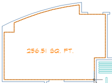
- After creating a closed polyline, launch the Field command ().
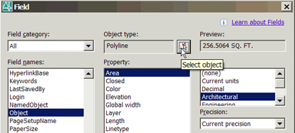
- From the list of Field names, select Object, then click the Select Objects button and select the closed polyline.
- The Field dialog box will re-open with a number of properties related to the selected object. The Area property is at the top of the list.
- Select a Format and a Precision from the lists on the right, then click OK.
- The Mtext indicating the area of the selected polyline is attached to the cursor. If you can't see the text, enter H for the Height option and enter the necessary value so you can see the text.
- Specify a location for the field.
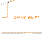
- Launch the Stretch command and change the shape of the polyline. In this exercise, I have increased the size of the area where a column or mechanical chase may be located in the upper left corner of the room.
- To update the field, regenerate the drawing.
Note: The variable Fieldeval specifies when a field is to be updated. (See ) The default value of 31 specifies that a field is to be updated when its associated information is modified.
To give credit where due, I found this trick on Shaan Hurley's website, http://autodesk.blogs.com/between_the_lines. His site has lots of links and AutoCAD tips and he's pretty diligent about updating his site several times per week.
For those of you doing civil engineering…
or creating golf courses in your spare time…
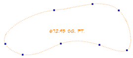
that field trick is a great way to keep track of the square footage of the area of a closed spline during the design phase of your project!
Power Tool
Global Prompt for Rotate
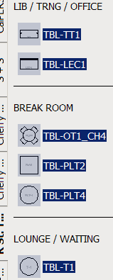
![]() In AutoCAD 2005 we were given the ability to assign a Prompt for Rotation property to blocks on a palette. The bummer is that the default setting is No. Now what person in their right mind wouldn't want the ability to rotate the block when it was placed on the drawing?
In AutoCAD 2005 we were given the ability to assign a Prompt for Rotation property to blocks on a palette. The bummer is that the default setting is No. Now what person in their right mind wouldn't want the ability to rotate the block when it was placed on the drawing?
Answer: The person far smarter than myself suggesting that the prompt for rotation would potentially "adversely affect" a dynamic block with a Rotate Action assigned to it. Point made. That still left me with a lot of blocks on a palette that were all set to 'No' for their Prompt for Rotation.
Solution: Hold down Ctrl, then click on a block on the tool palette. This effectively disables the process of placing the block in the drawing that usually occurs when you click on a block. That block is now selected.
Next, hold down Shift and click the last block in the column that you want to select (or use Ctrl and click individual blocks on the palette). If you have added Text or Separators (palette features available in A2006 only), use Ctrl and click those elements to deselect them.
Now right-click on any of the selected blocks and click Properties. In the Properties window, set the Prompt for Rotation to Yes, then click OK. All of the selected blocks now have their Prompt for Rotation set to Yes! How cool is that?
The Odd Spot
Global Updating of a Tool Palette Source File
 Some of you may be asked to create or customize tool palettes for your customers or perhaps you're the CAD Manager and have been working on your company's tool palettes at your home office. Regardless of the situation, when you add a block to the tool palette the source file is included in that block's properties. And in the current scenario, that source file just happens to be on a system other than where it will be when finally install your custom palette.
Quandary: You now have a couple dozen blocks on a palette (or palettes) with source files you will need to change once you turn it over to your customer (the Space Planning Dept. at CalPERS, for example) or your own corporate network. Can you do it globally? Yep.
I posted this question to the CADTutor Forum, and received an immediate response from Alan Henderson, one of the talented members of the support team at Resource CAD (www.resourcecad.com). Check it out.
Instructions to Globally Update a Source File Path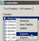
- You will first need to export the tool palette to create an .XTP file. Something you should do to any tool palette you create. Right-click on the Tool Palette window title bar, then click Customize.
- On the Tool Palettes tab, right-click on your tool palette, then click Export.
- Navigate to the location you want to save the .XTP file and click Save. The default name should be the name of the palette.
- Now go to Windows Explorer and open that file in Notepad (or Wordpad).
- It will look pretty intense, but you will notice the source file path throughout the code. Use (Ctrl+H) and enter the existing source file path, then the new path where the source drawing will be saved once you pass it along to the customer or take it back to the office.
When you copy the .XTP file onto the customer's system and Import the tool palette, the source drawing of the blocks will be recognized. Don't forget, of course, to bring along the .DWG file where the blocks live when you configure the new palettes.
The Basics
DesignCenter - Part III (Layout Fundamentals)
One of the most powerful features of the DesignCenter is the ability to access named objects (Layer, Dimension Styles, Text Styles, etc.) from any drawing (see The Basics in June 2005). Among that collection of drawing features in DesignCenter are the Layouts of a drawing.
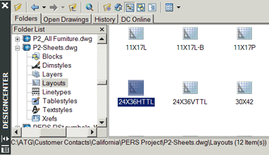
So consider this: Rather than putting all of the title blocks on their respective layouts and including those in your template (.DWT; see February 2004), how about having a separate drawing that contains only layouts. That way you access DesignCenter for the layouts as you need them.
Before I can show you the benefits of accessing Layouts from DesignCenter, I need to give you the fundamentals of creating a layout; something I should have done months ago. There are four essentials 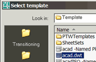 to configuring a layout: The device to which you will be plotting (a printer or plotter or in the case of the following example, a DWF driver), the paper size, a plot style table (usually monochrome or color) and the name you want to assign to the layout tab for easy recognition.
These fundamental elements are found in the same place for A2000-A2004. In A2005 & A2006, they re-arranged the "furniture" and shuffled their position, but the elements remain the same. Even for LT.
Instructions to Configure the Fundamental Elements of a Layout
- Open AutoCAD and click Use a Template and select the acad.dwt template. If AutoCAD is already open, click and select acad.dwt from the list.
- At the bottom of the drawing area are three tabs; Model, Layout1 and Layout2. Click on Layout1.
A2000-A2004: Depending on your current settings in Options, you may get the Page Setup dialog box. If you do, go to step 4 below. If you don't go to step 3 below.
A2005-A2006: Depending on your current settings in Options, you may get the Page Setup Manager dialog box. If you do, click Modify to go to the Page Setup dialog box. If you don't go to step 3 below.
- If your layout just appears with a rectangle in the middle of it (that's the viewport), right-click on the tab and click Page Setup or Page Setup Manager (depending on your version).
A2005-A2006: Click Modify to go to the Page Setup dialog box.

- A2000-A2004: On the Plot Device tab, select DWF ePlot.pc3 from the Name list of devices.
A2005-A2006: Select DWF ePlot.pc3 from the Name list of devices.

- A2000-A2004: On the Layout Settings tab, select ANSI B (17.00 x 11.00 Inches) from the list of Paper sizes.
A2005-A2006: Select ANSI B (17.00 x 11.00 Inches) from the list of Paper sizes.

- A2000-A2004: On the Layout Settings tab, select a style from the Plot Style list. Use acad.ctb/stb for color plots (aclt.ctb/stb for LT users). For a black and white output, select monochrome.ctb/stb .
A2005-A2006: Ditto.
- A2000-A2004: Click OK to close the Page Setup dialog box and see the result of your settings.
A2005-A2006: Click OK, then click Close from the Page Setup Manager to see the layout settings.
The viewport rectangle now appears smaller since the original page size was probably an A size and you have configured the layout to a B size (17 x 11).
- Right-click on the Layout1 tab and click Rename. Enter B size (17 x 11), then click OK.
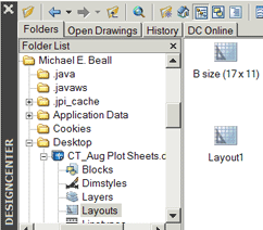
- To make this real easy, save this drawing to your Desktop (certainly not something I typically recommend), and name it CT_Aug Plot Sheets.dwg.
- To test this, open any AutoCAD drawing. Maybe you want to open one from the Sample folder or one you have recently worked on.
- A2000-A2002: Open DesignCenter and click on the Desktop icon on the toolbar at the top of DesignCenter, then navigate to the CT_Aug Plot Sheets.dwg and click the + sign to display the named object nodes.
A2004-A2006: Open DesignCenter. Depending upon your OS, you may need to go to C:\Documents & Settings \Yournamehere\Desktop to see the CT_Aug Plot Sheets.dwg file.
- Click on the Layouts node to display the layouts… which just happens to include B Size (17 x 11)
- To add that layout to the current drawing, you can either drag it into the drawing or just double-click that layout name.
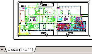
- Finally, click on the B Size (17 x 11) tab in your drawing, then double-click inside the viewport rectangle and use to see your drawing.
Like I said at the beginning, those are the very fundamentals. At least you now have a better handle on using Layouts from the DesignCenter and you may be making some mental leaps on how to optimally implement this approach to your title blocks.
Next issue we'll look at even more applications for DesignCenter!
Donate to CADTutor
If you found this article useful, you might like to consider making a donation. All content on this site is provided free of charge and we hope to keep it that way. However, running a site like CADTutor does cost money and you can help to improve the service and to guarantee its future by donating a small amount. We guess that you probably wouldn't miss $5.00 but it would make all the difference to us.
Note from Michael: I want to thank all of my customers for continuing to retain my training services (some for over three decades!) and let you know your donations do not go to me personally, but to the ongoing maintenance of the CADTutor ship as a whole and to support the yeoman efforts of my friend and CADTutor captain, David Watson, to whom I am grateful for this monthly opportunity to share a few AutoCAD insights.
The Basics
- Dual Dimensions in a Dim…
- UCSICON Options
- "Best of" Basics: Irreg…
- Tool Palette Basics
- Original Dimension Value
- Possible Solutions to th…
- Avoid Using 'Standard' i…
- Shorten the Plot Scales…
- Update the Source File B…
- User Increment Angles fo…
- Drawing Information
- 'Sign Language'
- Rotate with the Copy Opt…
- Use the INSERT Osnap on…
- To or From the Current L…


