

 Michael’s Corner #5
May 2003
Blocks Away!
To follow up the "Obscured" variables from last month, this month we take a look at a couple other features in AutoCAD that have 3D applications. In the Basics section you'll learn about some "special characters" that can be added to single-line text for commonly requested formatting. We begin this month with some technical insight into AutoCAD's Block tables that may answer some questions for which you had yet to nail down an answer.
If you would like to contact me directly, you can do that also.
Blessings to one and all,
Michael
Coming to Terms with Blocks
When you List a block, you see the term BLOCK REFERENCE. When you open the Block Definition dialog box using the Block command, you encounter the term "Block Definition". What's the difference?
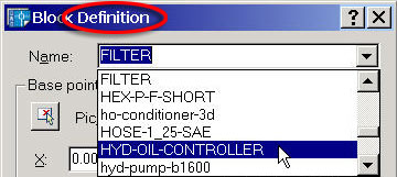
AutoCAD keeps track of the objects in a drawing using a variety of 'tables'. Two of the tables used for tracking blocks in a drawing are the Block Definition table and the Block Reference table. As it was explained to me years ago, think of the Definition table as containing a listing of "What" the drawing blocks consist of, such as their geometry and Base point location. Each block in a drawing has it's own unique block definition, such as the block named 'Filter' shown in this figure.. Therefore, the Definition table would be a listing of all the block names and their definitions.
Think of the Reference table as containing a list of "Where" the block references are in the drawing, including their insertion point, scale and rotation. The Reference table may contain the name of the same block many times, but each instance, or 'reference' will have its own X,Y,Z location, scale and rotation.
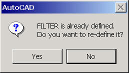 When you recreate a block and save it with an existing name, you will see a warning box. This is saying that the block Definition table has a block with this name. If you choose Yes to redefine it, all references of that block in the drawing will be updated with the new definition.
This ability to update a block globally can be a very useful feature. For example, you may be creating a drawing that has many references (instances) of a complex block. For speed and efficiency, it may be more convenient to work with a simplified version of the block. Once the drawing is complete, the block can be re-defined using the complex version.
Power Tool
MVSETUP
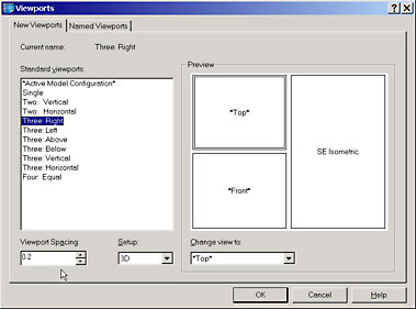
The old MVSETUP routine is still around but buried in the Viewports dialog (Vports command). To revisit this old friend, go into an empty Layout tab (delete any existing viewports), then launch the Vports (or Mvsetup) command. Change the Setup to 3D, then adjust the viewport spacing if needed. You can also choose the view to be displayed in each viewport using a drop-down listing. By default, the Three view drawings show you Top, Bottom and Iso in the standard locations.
When you click on OK, you pick the two corners within which the viewports are to be created, or press Enter for the default <Fit> option.
 |
 |
Curiously, to automatically scale the viewports, the Mvsetup command is the most efficient. Begin the command, then enter S for the Scale viewports option and follow the prompts:
Select the viewports to scale…
Select objects: Pick the viewports
Select objects: ![]()
Set zoom scale factors for viewports. Interactively/<Uniform>: ![]()
Set the ratio of paper space units to model space units…
Enter the number of paper space units <1.0>: ![]()
Enter the number of model space units <1.0>: Enter the desired value.
The Odd Spot
Isolines or Facetres?
It's a matter of what you desire to have as an end result. When you create a 3D solid cylinder, the number of lines displayed to define the sides of the cylinder is the value of the Isolines variable. The higher the number, the more lines are seen when you regen the drawing.
If you're just looking for a wireframe, adjust your Isolines setting to get the desired result. You can set it from 0 to 2047.
If, however, you would like to use the Hide command to get hidden lines, Isolines will do you no good. The variable Facetres is the one which adjusts the smoothness of the curved surfaces. The higher the number, the smoother the curvature. The range here is from 0.01 to 10.
Tip: If you want to get rid of the 'jaggies' when you do a hide, set the Dispsilh variable to 1.
The Basics
Special Text Characters
 There are five special character sets that can be used when using Dtext (Single-line Text) in your drawing.
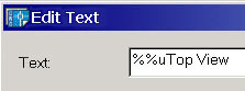
The Underline and Overline character sets can be placed at the beginning of the text string. As you see in the Edit Text dialog, the text to be underlined (or overlined) follows directly after the special character set.
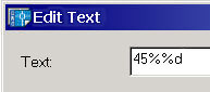
 For the Degree sign, Plus-minus sign and Diameter sign, place them in the text string where you want the special character to occur, as shown here with the 45 degree text.
 |
 |
Donate to CADTutor
If you found this article useful, you might like to consider making a donation. All content on this site is provided free of charge and we hope to keep it that way. However, running a site like CADTutor does cost money and you can help to improve the service and to guarantee its future by donating a small amount. We guess that you probably wouldn't miss $5.00 but it would make all the difference to us.
Note from Michael: I want to thank all of my customers for continuing to retain my training services (some for over three decades!) and let you know your donations do not go to me personally, but to the ongoing maintenance of the CADTutor ship as a whole and to support the yeoman efforts of my friend and CADTutor captain, David Watson, to whom I am grateful for this monthly opportunity to share a few AutoCAD insights.
Share this page:


The Basics
- Dual Dimensions in a Dim…
- UCSICON Options
- "Best of" Basics: Irreg…
- Tool Palette Basics
- Original Dimension Value
- Possible Solutions to th…
- Avoid Using 'Standard' i…
- Shorten the Plot Scales…
- Update the Source File B…
- User Increment Angles fo…
- Drawing Information
- 'Sign Language'
- Rotate with the Copy Opt…
- Use the INSERT Osnap on…
- To or From the Current L…


