

 Michael’s Corner #73
January 2009
Ready or Not, Here's 2009!
Funny thing about "Time"; it just keeps goin'. As I sit here in Kentucky on New Year's Eve in front of our Christmas tree, my friend Joshua in New Zealand is probably already celebrating 2009! Like giant, deliberate dominos, the midnight hours are striking those lines of longitude, heading your way.
New Things in 2009
Speaking of longitude, after years of training in the United States (including Alaska and Hawaii), I'll be training in Angola, Africa for a couple weeks in February, working with two teams at Chevron who are responsible for a vast array of drawings. That will add a fifth continent and an eighth country to my list of training locales, and will certainly be a new experience. Look for some insights in future articles from things I'm sure I will encounter over there.
Another idea I hope to implement before the year is out is at least one video clip included with an article every now and then. The Camtasia product makes it very simple to create videos, so our webmaster, David, and I will kick that around a little and see what we can do. I'll still have the instructions to follow along with, but a 15 or 20 second clip would be really cool, don't you think?
And finally, before summer, I hope to publish a compilation of all of the Michael's Corner articles from 2003 thru 2008. Tentatively titled, "Michael's Corner: The First Six Years", I'll organize and update all the articles to be applicable for A2008 thru A2010. After a brief poll, it appears that you would rather have a hard copy that you can highlight, sticky-note, dog-ear, and take notes in, rather than a PDF file. If you have any suggestions, I'd love to hear from you.
Ah, yes, and this month continues with a custom button for your ever-growing tool palette, along with a quick trick to modify the attribute definitions of a block. In the Odd Spot I show you how to get that Startup dialog box back as well as a buried command to let you identify who has the drawing open that caused you to get the Read Only box. And finally, I think I may have clarified why that Breakline command from the Express Tools never quite worked out for you.
I hope your New Year is off to a fabulous start!
If you would like to contact me directly, you can do that also.
Blessings to one and all,
Michael
Editing Existing Attribute Definitions
 Let's say you're updating your existing attributed title block or sheet borders and you need to change the prompt or maybe the position of an attribute. Here's what I just passed along to one of my customers and thought you may be interested.
The Block Editor was introduced in A2006 when Dynamic blocks arrived and I have found it to be a more user-friendly method of editing blocks - dynamic or otherwise - than the Refedit command.
Instructions to Modify an Attribute Definition
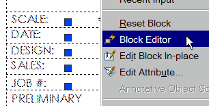
- Single click on the attributed block to be modified, then right-click and click Block Editor.
 Tip: If you have not opened the Block Editor previously, you may get a dialog box regarding learning more about Dynamic Block and the Editor. You can click No at this time. You can also check the box in the bottom left corner to suppress that dialog box in the future.
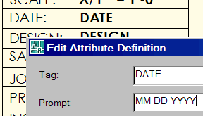
- At this point you have free reign on the block geometry. To modify an attribute definition (the point of this exercise), double-click the desired definition to open the Edit Attribute Definition dialog box and make your edits. In this example, I included a date format in the Prompt to remind the designers of the company standard.
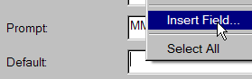 Gold star tip: Right-click in the Default text box of the Edit Attribute Definition dialog box, then click Insert Field. Field text can be used to automatically place the Drawing name, Create Date, Plot Date, etc. in the specified location. See the Main article in Michael's Corner, July 2005 for the use of Fields.
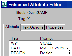 After making the necessary modifications to the block, click Close Block Editor (located in the middle of the Editor toolbar) and save your changes. Now when you edit the attributes of the block, you will see your changes.
Power Tool
Custom Button #11: Restore a Layer State
For those of you following my Custom Button parade and wondering what happened to #10, technically, the main article in October 2008 - Select Object for a Hatch on a Button - was number 10.
Every time I train folks on the practical application of layer states, they really get excited (see Michael's Corner, February 2007 for a quick review on creating layer states). Since my contract furniture customers are frequently interested in restoring a layer state of a "Panel Plan", let's take a look how that would work on a button. You may want to make a couple layer states first, then check it out.
Instructions to Add the Layer States Manager Tool to a Palette
- Open the Layers toolbar and also open the Tool Palette window. (A2009 users that only use the Ribbon may want to open the CUI and get the icon from there.)
- Right-click on the title bar of the Tool Palette title bar (or in between icons on the palette) and click Customize Palettes to open the Customize dialog box.
- Move the Customize dialog box aside, it's simply the key to get in the "door" for the process of copying a button to the palette.
- Click and drag the Layer States button from the Layers toolbar and drop it onto your palette. Now you can Close the Customize dialog box; it has served its purpose.
- Right-click on the new Layer States button on the palette, then click Properties to open the Tool Properties dialog box.
- First, you may want to change the name of the button.
- Edit the Command String to read as follows, substituting a valid layer state name in the quotes where I have "Panel_Plan":
^C^C-LA;A;R;"PANEL_PLAN";;;
| ^C^C | Cancel; essentially hits the ESC key |
| -LA | Launches the command line version of the Layer command |
| ; | The semi-colon means press <Enter> |
| A | The Layer StAte option of the Layer command |
| R | The Restore option |
- After editing the Command String, click OK to close the dialog box.
To test your button, you may want to turn some layers On/Off or restore a different layer state, then try it.
The Odd Spot
Startup & Whohas
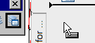
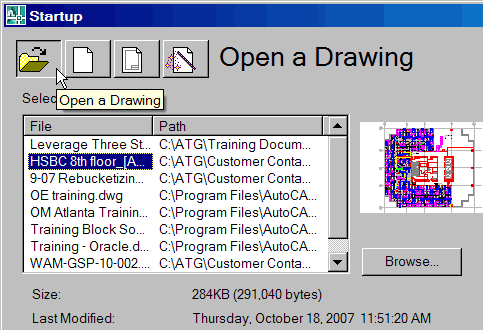 Every now and then I encounter veteran users who still prefer the Startup dialog box, from which they can choose from a variety of templates or simply Browse another folder and select a drawing other than the last 9. Curiously, it's no longer an option in the Options dialog box since (I think) A2007.
If this is something you have been wondering about and how to get it back, you will want to set the STARTUP variable to <1>, then close and re-launch AutoCAD. That should make your New Year a little Happier!
And while we're talking about random features, have you ever wondered which one of your associates has a drawing open that has caused you to get the "Read Only" notice??
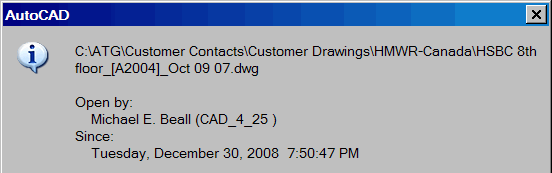
When you run the WHOHAS command, the Select File dialog box opens and you can choose the drawing of interest. You are then presented with the dialog box with the path and filename, along with the person who opened it… and when.
The Basics
EXPRESS: Breakline + Symbol
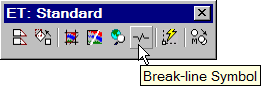 There's this wonderful little command in the Express collection called ‘Break-Line Symbol’ that works like a champ. The name is misleading since it creates the line and inserts the zigzag symbol.
Here's a breakdown of the command and options:
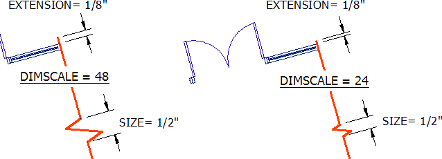
Block= BRKLINE.DWG, Size= 1/2″, Extension= 1/8″
Specify first point for breakline or [Block/Size/Extension]: Change S/E options here.
Specify second point for breakline:
Specify location for break symbol <Midpoint>:
| Block= BRKLINE.DWG | This is fine; leave it. |
| Size= 1/2″ | Size of the break symbol x the current Dimscale value. |
| Extension= 1/8″ | Distance beyond the pick points x the current Dimscale value. |
Instructions to Add the Breakline & Symbol
- Set the desired Layer and Dimension Style, then launch the Break-line Symbol command from the Express
 Draw menu or from the ET: Standard toolbar.
 - At the first prompt, change the Size or Extension values as necessary, then pick the first and second points for the breakline. (Keep in mind the command will then extend the breakline beyond the pick points.)
- When placing the break symbol, the command incorporates the Nearest object snap, so you can place the break anywhere. If you want the break to be exactly at the midpoint of the breakline, press [Enter] to accept the <Midpoint> default option.
My suspicion is that most folks never got past playing with this command since they didn't realize the Size and Extension were multiplied times the current Dimscale. The figures show the results of two different Dimscale values with the default Size and Extension settings.
It won't take you long to find what works for your drawings and you'll be on your way to consistent breaklines!
Left Field
Herman Miller, the man [c. 1905] - Among the many furniture companies in West Michigan in 1905, one was called Star Furniture Company and employed a gentleman by the name of DJ DePree. When the owner expressed a desire to sell out, DJ decided he would buy it; specifically "how" was the problem. DJ was married to Nellie Miller and, after seeking elsewhere, he approached is father-in-law, Herman. No doubt desiring the best for his daughter, Mr. Miller came up with the cash for DJ to buy the company. Out of respect for his benefactor, DJ named the company The Herman Miller Furniture Company. So now ya know.
Donate to CADTutor
If you found this article useful, you might like to consider making a donation. All content on this site is provided free of charge and we hope to keep it that way. However, running a site like CADTutor does cost money and you can help to improve the service and to guarantee its future by donating a small amount. We guess that you probably wouldn't miss $5.00 but it would make all the difference to us.
Note from Michael: I want to thank all of my customers for continuing to retain my training services (some for over three decades!) and let you know your donations do not go to me personally, but to the ongoing maintenance of the CADTutor ship as a whole and to support the yeoman efforts of my friend and CADTutor captain, David Watson, to whom I am grateful for this monthly opportunity to share a few AutoCAD insights.
Share this page:


The Basics
- Dual Dimensions in a Dim…
- UCSICON Options
- "Best of" Basics: Irreg…
- Tool Palette Basics
- Original Dimension Value
- Possible Solutions to th…
- Avoid Using 'Standard' i…
- Shorten the Plot Scales…
- Update the Source File B…
- User Increment Angles fo…
- Drawing Information
- 'Sign Language'
- Rotate with the Copy Opt…
- Use the INSERT Osnap on…
- To or From the Current L…


