

 Michael’s Corner #115
July 2012
Whiz-Bangs & Congratulations
Sometimes when people are using AutoCAD, it can appear like it's all smoke and mirrors: "How did they DO that?"
Well, that's why they call it ‘Training’.
David Watson and I — David being the captain of this amazing CADTutor website — are in the business of education, and it thrills us both to be able to ‘turn the lights on’ for our customers and classes. We love to take what looks like Whiz-Bang and show folks how to it all works.
That said, I want to extend a hearty "Congratulations" to all those whose proposals were recently accepted for Autodesk University 2012, being held in Las Vegas November 27 – 29. AU is one big Whiz-Bang conference where top educators ‘turn the lights on’ for thousands of attendees. I opted out this year, but I heard from a couple of my close friends and was quite pleased to hear of the acceptance of their classes. Quite the honor, to be sure.
This months' Corner has a few Whiz-Bangs of its own, namely…
…How to use the 3D Gizmo to rotate objects in 3D
…A2013 updates to the Presspull command
…Uncovering the mystery of why a Solid hatch may not display
…Why you may want to use the As Displayed feature for a viewport
Hope you are all enjoying this season!
[And congratulations to my son, Joshua, who got all A's last quarter in his Digital Filmmaking courses at the Art Institute in Cincinnati!]
If you would like to contact me directly, you can do that also.
Blessings to one and all,
Michael
3D Rotate with the Rotate Gizmo
A customer contacted me about a 3D furniture block they had that was laying on its back when they opened the drawing, and wondered how to rotate it in 3D. My thought was to use the 3D Gizmo for Rotate to flip that thing back onto its feet.
Prerequisite: Visual Style set to Shades of Gray. It's easier to see the rotation and the 3D Gizmos if you don't have so many other colors competing for your attention.
How to Rotate a 3D Object in 3D
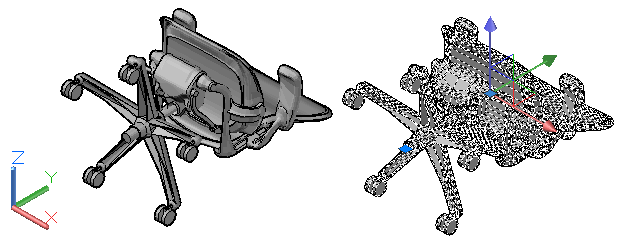
On the View tab, set the Visual Style to Shades of Gray.
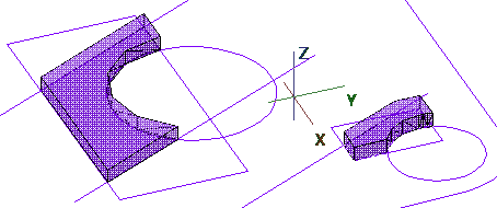
Click on the object to rotate, and the Move gizmo will be displayed with the arrows for the 3 axes as seen in the first figure.
For the Rotation gizmo, right-click on one of the axes, then click Rotate to display the Rotate gizmo (three "hoolahoops" around the geometric centroid of the selected object).
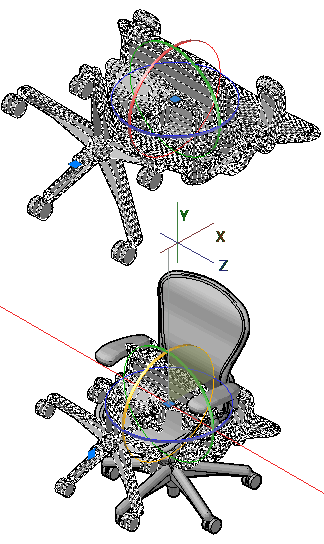
Click on the circle that addresses your rotation requirements — the red one for this exercise. It turns yellow and you see a red line defining the axis of rotation.
Turn on Ortho or Polar if needed, then rotate your object to its final position. As you rotate the object, the arc of rotation is shaded if you're able to see it. It's yellow in this final illustration.
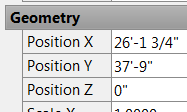 If you then need to reposition the object to 0,0,0, you can always use Properties (Ctrl +1), then under Geometry, set the Position values as needed.
Power Tool
Presspull on an open Polyline
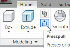 Found in the 3D Modeling workspace [Home tab
![]() Modeling panel], the Presspull command — originally covered in Michael's Corner, December 2006 — has always been a favorite of mine. It had a bit of an overhaul in AutoCAD 2013, however. Many folks are aware of the Extrude command, but there are 2 reasons why I prefer to use Presspull instead:
Modeling panel], the Presspull command — originally covered in Michael's Corner, December 2006 — has always been a favorite of mine. It had a bit of an overhaul in AutoCAD 2013, however. Many folks are aware of the Extrude command, but there are 2 reasons why I prefer to use Presspull instead:
The Extrude command incorporates the original 2D primitive geometry into the resulting solid.
The Extrude command requires a closed Polyline to extrude.
The Presspull command, on the other hand:
Retains the integrity of the original, 2D geometry used to create the solid.
Requires only that the area being ‘pressed’ or ‘pulled’ be closed.
If you have AutoCAD 2012, the list stops there. If, however, you have AutoCAD 2013…
You can create an Extruded surface from an open Polyline!… and…
You can select more than one object to be pressed or pulled!
Caveat in AutoCAD 2013: When selecting multiple objects for Presspull, the selections must be of the same condition, i.e., open polyline, closed polyline, or enclosed area created by multiple objects.
How to Use Presspull in AutoCAD 2013
Create any enclosed area using any combination of lines, circles, and rectangles.
Take a 3D view position, such as Southeast, then launch Presspull.
Click inside an enclosed area, then enter M for the Multiple option.
Click inside additional open areas, then press [Enter].
Move to see the creation of the new solids, then specify the 2nd point or enter a distance.
Create a couple of open polylines, then use Presspull with the Multiple option on those.
The Odd Spot
FILLMODE <1> for Solid Hatch
It's difficult to illustrate the effect of something that doesn't work, but suffice it to say if the variable FILLMODE has mysteriously been set to <0>, you'll know right away.
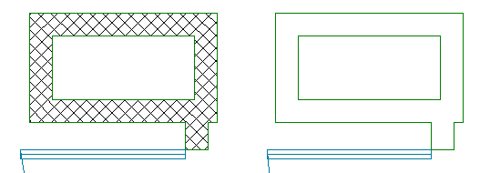
FILLMODE: Specifies whether hatches and fills, 2D solids, and wide polylines are filled in. Saved In: Drawing
There's the odd thing that was messing with my customer. The hatch would appear in one drawing just fine, but when she went to hatch in the other drawing, zip. Because it was Hatch related, I was going through all the HP* variables — Hatch Pattern, of which there are many — but her settings were the same as mine and my system was hatching just fine.
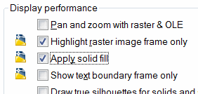 Then I hit on the *FILL* variables because TEXTFILL is a nasty one that is quite annoying (although that one's saved in the Registry), and that's when I came across FILLMODE. A wee bit of research using Help and I found that it's a setting on the Display tab of the Options dialog box, under Display Performance… or lack thereof.
Note: Anytime you see a drawing icon beside a setting in Options, it means that setting is DWG-specific.
The Basics
Visual Styles and ‘As Displayed’
While we're on the subject of curious ‘fill’ conditions, many of you have probably encountered the Outline result when plotting from a Layout tab with a Text Style in Model space that uses the Arial font, as shown in these figures.
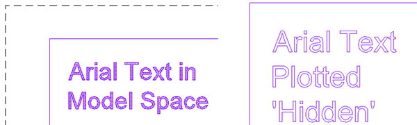
The solution: If you must have hidden lines in your viewport, then in Model space, set the Visual Style to Hidden.
How to Set the Visual Style and Plot ‘As Displayed’
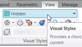 On the View tab of the Ribbon, Visual Styles panel, click in the styles dropdown list and click Hidden.
On the Layout tab, click on the edge of the viewport frame, then right-click, ‘As Displayed’.
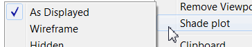
Now when you plot, you will have hidden lines in your viewport and the Arial font — and other ‘filled’ TrueType fonts — will display properly.
Left Field
What a Monster
Los Angeles, actually. I found it amazing that it took me as long to just get to the other side of this mega-politan area (I just made that up, you can use it), as it does to drive up from our home in Kentucky to see our son in Cincinnati; 90 minutes. So here are a few tidbits about the region broadly referred to as "Los Angeles".
– The Los Angeles five-county area has a population of almost 20 million. It includes Los Angeles, Riverside, Ventura, Orange and San Bernardino Counties.
– If the five-county Los Angeles area were a state, it would be the fourth largest in the United States.
– When Los Angeles was founded in 1781, 44 people (14 families) lived in El Pueblo de Nuestra Senora la Reina de Los Angeles de la Porciuncula (Town of Our Lady the Queen of the Angeles of the Small Portion). The population grew, but the name shrank to simply "Los Angeles".
Donate to CADTutor
If you found this article useful, you might like to consider making a donation. All content on this site is provided free of charge and we hope to keep it that way. However, running a site like CADTutor does cost money and you can help to improve the service and to guarantee its future by donating a small amount. We guess that you probably wouldn't miss $5.00 but it would make all the difference to us.
Note from Michael: I want to thank all of my customers for continuing to retain my training services (some for over three decades!) and let you know your donations do not go to me personally, but to the ongoing maintenance of the CADTutor ship as a whole and to support the yeoman efforts of my friend and CADTutor captain, David Watson, to whom I am grateful for this monthly opportunity to share a few AutoCAD insights.
Share this page:


The Basics
- Dual Dimensions in a Dim…
- UCSICON Options
- "Best of" Basics: Irreg…
- Tool Palette Basics
- Original Dimension Value
- Possible Solutions to th…
- Avoid Using 'Standard' i…
- Shorten the Plot Scales…
- Update the Source File B…
- User Increment Angles fo…
- Drawing Information
- 'Sign Language'
- Rotate with the Copy Opt…
- Use the INSERT Osnap on…
- To or From the Current L…


