

 Michael’s Corner #6
June 2003
Attribute! - bless you
In keeping with a few block-related articles, this month Michael gives a few attribute insights for those of you looking to understand them a bit more. For those of you working with drawings from the outside, you may find the Rename dialog box to be of interest. It has been around since R11 but relatively unknown or rarely used. It's very useful in renaming Xref layers or blocks. Rounding out this month is some information on a Fillet variable, along with an introduction to Named Views, another under-appreciated feature that's been around awhile.
If you would like to contact me directly, you can do that also.
Blessings to one and all,
Michael
The Fundamentals of Attributes

Attributes are fine for automating the placement of drawing Name, Drawn by, Rev number, etc., but what about adding door or sprinkler head information to a block so you can run a take-off later? For those of you with the gloves off and just slugging your way through AutoCAD, let's look at a way to add attributes to a block. Next month, we'll track those blocks and the attributes assigned to them.
AttDef Basics
To add attributes to a block (or .dwg file you Wblock out), you need to define the attribute(s) prior to using the Block or Wblock commands. Type Attdef at the command line and you get the Attribute Definition dialog box. Each attribute must be defined, therefore, each of the four attributes associated with the ellipse in the figure required the use of the Attribute Definition dialog box for their definition.
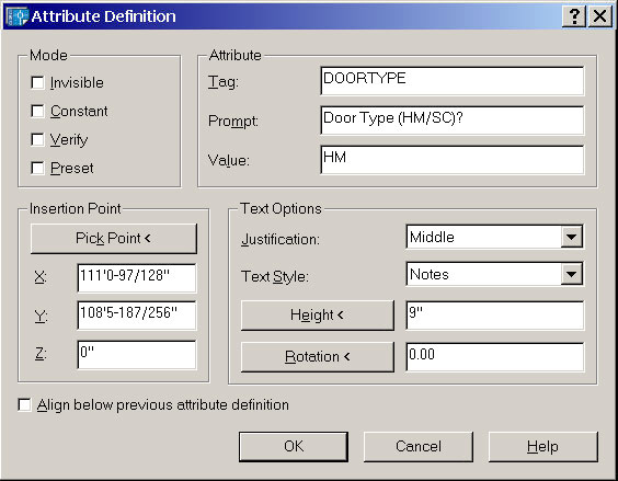
Mode frame:
Invisible - Most commonly used for data that need not appear in the drawing but can be extracted later.
Constant - A variable that can be edited, but is typically the default condition.
Verify - Will give the user what I call an "idiot check" by prompting "Are you sure?" after the value is entered.
Preset - The value is uneditable but needs to be associated with the block.
Attribute frame:
Tag - No spaces; something generic.
Prompt - What do you want the command line to say when the block/file is inserted?
Value - You may want to define the attribute with a default value that is the most common. In the figure, a hollow metal (HM) door may be more common than solid core (SC). If a format of text entry is required, you may want to the default text to read nn-xx-01.
Text Options frame:
Justification - Your call.
Text Style - Choose from the available text styles of the current drawing. Thankfully, when your attributed file/block is inserted into another drawing, if that host drawing does not contain the specified text style, it is automatically created.
Height & Justification - Enter the values or pick the buttons and graphically indicate the values.
Insertion Point frame:
Pick Point - Pick the button and pick the base point position for the first attribute text. The justification is per the Text Options "Justification" setting.
Note: After picking the insertion point for the first attribute text, check the "Align below previous attribute definition" box for successive placement of vertically aligned attribute text and they'll line right up, single-spaced (but you can move them later if need be).
Application
Once you have created the attributes, use Block or Wblock and include the text in the selection.
Tip: If you need to edit the Tag, Prompt or Default fields, simply double-click on the attribute text and make the edits in the Edit dialog.
 Insert the block into the drawing using the Insert command or DesignCenter. After specifying the insertion point you will be prompted for the attributes you defined for that block!
Enter attribute values
Enter door number <XXXA>: 0603
Door Type <HM>:
Frame Type <HM>:
Lockset ID <#24>:
Power Tool
DDRENAME
DDRENAME [Alias: REN] was originally introduced in Release 11 to provide the AutoCAD user a method by which to rename what AutoCAD refers to as "Named Objects"; things that are named but may or may not have an object-based presence in the drawing, such as a layer or a view (see this month's Basics section).
In my training sessions, I will frequently suggest to my customers that, as soon as they get a drawing from the outside, they go to the Rename dialog to see what they just "inherited". This dialog provides a quick glimpse at the name of every Block, Dim Style, Layer, loaded Linetype, Text Style, named UCS, Viewport, and View in the drawing.
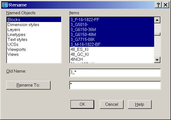
It's most powerful feature, as the name would indicate, is the ability to potentially globally rename blocks or layers with a common prefix. In the illustration, you see in the Old Name field the 3_* characters to request that all blocks beginning with 3_ be selected. In the Rename To field, the * is requesting that the new block names would be changed to the characters which occur after the 3_.
RENAME 57 Blocks renamed
There is a downside, albeit, workable: If there are one or more resulting block names (or whatever named object you choose to rename) that would conflict with an existing name, the procedure is aborted. The workaround would be to simply confirm the possibility and individually rename the errant object.
I have frequently used this tool to rename a block in which there may have been a typo in the name when it was created or if, upon reconsideration, I wanted it to use the name for another block.
The Odd Spot
Offset Corner Types
When you offset a polyline, you get, essentially, a concentric copy of the selected object. There are two additional modes that you may want to consider, based upon your application. The variable Offsetgaptype enables you to preset the corner of the resulting offset to a fillet with a radius equal to that of the offset, or a chamfer with distance 1 and 2 equal to that of the offset.
 |
 |
 |
| Offsetgaptype <0> | Offsetgaptype <1> | Offsetgaptype <2> |
As you see in the illustrations, the original "L" shape was offset a distance of 4 units with the default Offsetgaptype value of 0. Set to a value of 1, the offset fillets the corners (R=4). Set to a value of 2, the resulting offset corners are chamfered.
The Basics
Saving Named Views
Even though you can return to the 10 previous displays with Zoom/Previous, it may be more advantageous to save a specific display of your drawing by name. If, for example, you are responsible for a plant layout and find that there are certain areas on that drawing to which you return frequently, save the display of that area by name using the View command.
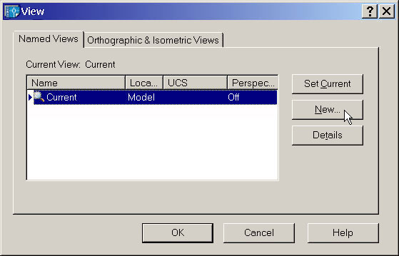
The most efficient approach is to zoom into the specific area and choose Named Views from the Standard toolbar if you are using pre-A2004 (in AutoCAD 2004 it was dropped from the Standard toolbar so you will need to enter V at the Command line or choose View/Named Views from the pulldown menus).
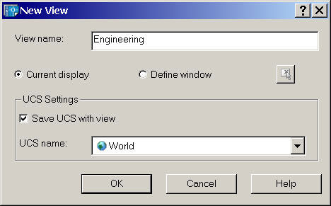
In the View dialog box, click on the New button to open the New View dialog box. In the View name field, enter the name of the view, then click OK. Note: You are not saving the image or creating a file. AutoCAD effectively takes the X,Y coordinates of the lower left and upper right corners of the screen and puts them in a "shoebox" and labels it with the view name. You can have as many named views as you would like per drawing. After working in the drawing and changing your display, when you return to the View dialog, select the named view, click Set Current, then OK, AutoCAD sets the X,Y coordinates for the display corners to those that were current when you saved the view (the ones from the "shoebox" with that name).
Idea: Save a named view in Model space (such as a 3D view), then switch to a viewport in a Layout and restore the named view in that viewport.
Tip: You can plot a named view!
Donate to CADTutor
If you found this article useful, you might like to consider making a donation. All content on this site is provided free of charge and we hope to keep it that way. However, running a site like CADTutor does cost money and you can help to improve the service and to guarantee its future by donating a small amount. We guess that you probably wouldn't miss $5.00 but it would make all the difference to us.
Note from Michael: I want to thank all of my customers for continuing to retain my training services (some for over three decades!) and let you know your donations do not go to me personally, but to the ongoing maintenance of the CADTutor ship as a whole and to support the yeoman efforts of my friend and CADTutor captain, David Watson, to whom I am grateful for this monthly opportunity to share a few AutoCAD insights.
Share this page:


The Basics
- Dual Dimensions in a Dim…
- UCSICON Options
- "Best of" Basics: Irreg…
- Tool Palette Basics
- Original Dimension Value
- Possible Solutions to th…
- Avoid Using 'Standard' i…
- Shorten the Plot Scales…
- Update the Source File B…
- User Increment Angles fo…
- Drawing Information
- 'Sign Language'
- Rotate with the Copy Opt…
- Use the INSERT Osnap on…
- To or From the Current L…


