 Michael’s Corner #22
October 2004
Power Edits and Buried Treasure
As I was presenting an AutoCAD workshop to an architectural firm in Colorado Springs, Colorado last month (www.rtaarchitects.com), I came to the startling realization that I had failed to present some very fundamental, yet powerful features in the pages of this column. I will frequently use the archives of this column (found at the bottom of this page), when a question is brought up during a training session…
The Align and Lengthen utilities are under-utilized mostly because folks don't know they're out there. One of the more misunderstood features is Pedit, a feature that may take a couple months to fully review. Also, the Region command has been around since R11, I think, and believe it or not, is part of AutoCAD LT. And LT even has the three Booleans of Intersect, Union, and Subtract.
If you would like to contact me directly, you can do that also.
Blessings to one and all,
Michael
Align
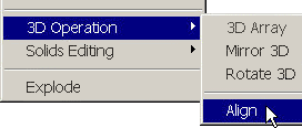 The Align command is buried in the 3D Operation section of the Modify menu so not a lot of people even know it's out there. It's a very intuitive procedure that accomplishes a Move + Rotate based upon two sets of points.
Instructions to Align Selected Objects
- Begin the Align command [AL] and select the objects, then press ENTER.
Note: There is no button for this command so you'll have to make your own if you want one.
- Pick the first source point on the selected objects. This point will be physically moved to the first destination point.
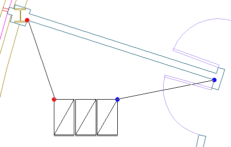
- Pick the first destination point which will effectively be the "anchor point". Each of these points are indicated with the red dots in the figure.
- Pick the second source point on the selected objects. This point will be essentially "aimed toward" the second destination point (the blue dots in the figure).
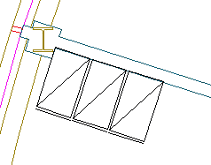
- Pick the second destination point. The second pair of points are indicated with the blue dots.
- When prompted for the third source point, press ENTER to continue on to the next prompt.
- Since most of you will be using this for a Rotate/Move, press ENTER (for NO) when prompted to scale objects based on alignment points.
AutoCAD will then whip the selected objects up against the vector defined by the first and second destination points.
Tip: For quick edits once the objects have been aligned, use UCS/OBject, then select the line along which the objects were aligned. This rotates the UCS so you can use Move or Copy with Ortho on and keep them at that angle.
Power Tool
Lengthen
The LENGTHEN [LEN] command has come in handy a number of times in my contract drawings, especially in those times when I need to maintain the vector of the line, but simply need to modify the length. I use it sometimes just to find the length of a line and it's quicker than using List or the Properties window if I have several objects to query.
Options: Launch the Lengthen command, choose a line, arc, or open pline to see the following:
Select an object or [DElta/Percent/Total/DYnamic]:
Current length: 6'-1 7/16"
DElta - If the length of the object selected requires "amending", use this feature and enter the desired additional length or enter a negative value by which to reduce the length. When prompted to select the object to change, pick on the end of the object nearest to where you want the addition (or subtraction) to be applied.
Tip: When using the DElta option, each time you click the object, the value is applied.
Percent - Enter a positive, non-zero value, then select the object.
 Total - This one is great if you're working on an existing drawing and the "as-built" value is different than that shown in the drawing. Similar to the DElta feature, the adjustment to the object will take place on the nearest end of the object you select.
Total also has an Angle option in the Lengthen command in which you can enter the total desired angle of an arc, (an uneditable value in the Properties window).
 DYnamic - It took me a minute to figure out what it was doing, but when you use this realtime feature, imagine a perpendicular line going from the crosshair to the end of the line being edited. And yes, you can snap to an object when using this option.
Tip: Although circles and closed plines are uneditable with Lengthen, their "current length" will still be displayed when selected.
The Odd Spot
Region
 For lack of a better description, a Region is a 2D solid. That sounds like an oxymoron, but a Region is an opaque, planar solid. Draw any closed shape on a piece of paper, cut it out, and you essentially have a region. Unfortunately, very few folks know what it does or how to make one. Here's the simplest method by which to create a region, a procedure that is available in AutoCAD as well as AutoCAD LT.

- Draw a circle, rectangle, polygon, or any closed polygon.
- Click Region on the Draw toolbar, select the shape(s), and press <Enter>.
If the shapes are individual, the command will convert each shape into a region.
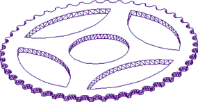
Now what? Let's say you are making a sprocket and you need to create a single object. In the figure, you see 6 shapes; each one of which has been turned into a region. You could create a named group, but that would be nothing more than a unique collection of shapes.
 To create voids from the five interior shapes, subtract those five shapes from the outer wheel of the sprocket using the Subtract feature found on Solids Editing toolbar or from the Modify menu.
- Select Subtract and notice the prompt is first to select the "solids and regions to subtract from…", then press <Enter>.
- Now select the shapes to subtract, then press <Enter>.
You now have a single region with five voids. In the Properties window you will see the surface area and perimeter listed and you can now use the Extrude routine as shown in the 3D image.
The Basics
Polyline Edit
 In the February 2004 and April 2004 articles, I mentioned a couple polyline-related features, but I have failed to mention how you can convert lines into polylines in order to take advantage of the benefits of polylines.
First, by way of analogy, geometry created with the Line command is similar to toothpicks laid end to end. It's a collection of line segments whose endpoints are co-incident.
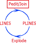 Polylines, however, have knuckles; they're connected at their endpoints. To convert lines to polylines…
- Launch the Pedit command (found on the Modify II toolbar, or from ).
- Select one of the lines to be converted into a polyline, then press <Enter> to accept the default option of Yes and turn the selected line into a polyline.
Tip: In AutoCAD 2004/2005, to suppress the prompt “Do you want to turn it into one?” that occurs after selecting the line to edit, set the variable PEDITACCEPT to <1>.
- You will now see several options:
[Open/Join/Width/Edit vertex/Fit/Spline/Decurve/Ltype gen/Undo]
- Enter J for the Join option, then select the additional lines that are to be joined with the line first selected. You can window the objects to be joined since AutoCAD will only join contiguous line segments.
Next month I'll take a look at some of the other Pedit options and their relationship with other AutoCAD features.
Donate to CADTutor
If you found this article useful, you might like to consider making a donation. All content on this site is provided free of charge and we hope to keep it that way. However, running a site like CADTutor does cost money and you can help to improve the service and to guarantee its future by donating a small amount. We guess that you probably wouldn't miss $5.00 but it would make all the difference to us.
Note from Michael: I want to thank all of my customers for continuing to retain my training services (some for over three decades!) and let you know your donations do not go to me personally, but to the ongoing maintenance of the CADTutor ship as a whole and to support the yeoman efforts of my friend and CADTutor captain, David Watson, to whom I am grateful for this monthly opportunity to share a few AutoCAD insights.
The Basics
- Dual Dimensions in a Dim…
- UCSICON Options
- "Best of" Basics: Irreg…
- Tool Palette Basics
- Original Dimension Value
- Possible Solutions to th…
- Avoid Using 'Standard' i…
- Shorten the Plot Scales…
- Update the Source File B…
- User Increment Angles fo…
- Drawing Information
- 'Sign Language'
- Rotate with the Copy Opt…
- Use the INSERT Osnap on…
- To or From the Current L…


