 Michael’s Corner #28
April 2005
Views, Layers and 3D in LT?
The features this month are some of those things that are buried more than one level deep or just don't lend themselves to being the most obvious. For example, creating named views: Check. Naming a UCS position: Maybe. Combining the two: Seriously? Oh, yeah. Then there's the whole Layer State thing that has now been relegated to a graphic button in AutoCAD 2005/2006, rather than the text "Save State" as in previous versions. A feature that doesn't really come on to the radar when you're in that dialog box.
And then there's AutoCAD LT. Not "Lite" by any stretch, just a moniker that originally stood for "LapTop" when first released but got turned around to "Lite" since it had a reduced command set than the full version. (At the time when it was released, laptops had whopping 10Mb hard drives and you paid dearly for a meg of RAM so there was no way the big dog was going to operate smoothly in that environment). I've been doing quite a bit of training on LT for my customers across the U.S., so I thought I'd tell you about the little-known fact that AutoCAD LT is actually a 3D environment… and I'll prove it. Let me know what you think.
If you would like to contact me directly, you can do that also.
Blessings to one and all,
Michael
Saving Views with the UCS
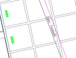 If you use named views in your drawings, you will be able to more effectively zoom to an area you frequently access. This is particularly useful in mapping applications or those drawings with multiple angles. In the Basics article of my June 2003 column I presented the fundamentals of named views.
To kick it up a notch, what if you have rotated the drawing view by repositioning the UCS as discussed in my lead article in the August 2004 column [Ditto, thanks]. Now let's combine the two features. After rotating your drawing view by changing the orientation of the UCS, save the UCS by name as well as the View. By doing so, when you restore the view, the UCS position will also be restored.
Note: The naming of a UCS can only be done from the UCS command line. Curiously, this is still the case in AutoCAD 2006; there is no dialog box in which you can click a "New" or a "Save" button to name a new UCS position.
In the following procedure, you will need a drawing with at least one line at a non-orthogonal angle. If you're starting from scratch, just draw a diagonal line and go from there.
Instructions to save a UCS position with a named view
- To rotate the display to be parallel with a diagonal line, select , then click on the diagonal line you wish to bring parallel to the X-axis.
- To reorient the view of the drawing, select . Because this procedure incorporates a , you may now need to zoom closer to the area.
- At the command line, type UCS and press [ENTER]. To save a UCS position with a name, type S and press [ENTER].
- Enter a name for the UCS, then press [ENTER]. In the example, I named the UCS "Grid".
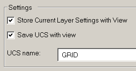
- Once the UCS position has been named, select , then click the New button. You will see that the name of the UCS is displayed at the bottom of the New View dialog box and the default setting of "Save UCS With View". Enter a name for this view. In the example, I named the view "Planting Grid".
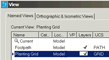
- Click OK after you have entered a View name and you will see the view name and the associated UCS in the list. Click OK to close the View dialog box.
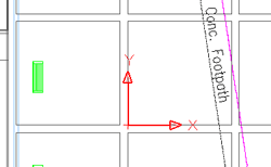
- To text your procedure, use to go back to the original display of your drawing. To set the UCS position back to World, select .
- Now check your View and UCS by going to and select your named view in the list, then click Set Current. You could also double-click the name; as long as the little pointer moves down to your view name.
- Click OK and the drawing display returns to that view… and the UCS comes with it!
Power Tool
Maximize Viewport

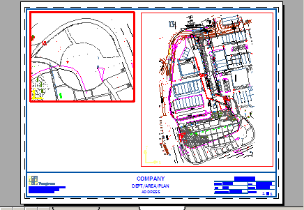
Those of you familiar with viewports on a Layout tab will relate to this. You have a small viewport on your layout, but you need to just jump in there for a minute, make a quick fix, then jump back out. The bummer is, when you come back out, you will probably need to restore the plot scale of the viewport, and if the viewport is locked, you will have to unlock it before you can pan and zoom. For that reason, many of us just click back on the Model tab, make the edits or whatever, then click back on the Layout tab and go from there.
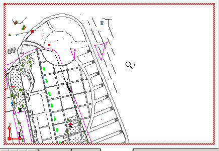
AutoCAD 2005 introduced the Maximize/Minimize Viewport button on the AutoCAD status bar for just these occasions. When you click into a viewport, then use Maximize Viewport not only does it maximize the frame of the viewport to the entire drawing window (with red 'stitching' around the edges),  it will also temporarily override the locked status of that viewport to let you pan and zoom.
But don't panic, when you click the toggled Minimize Viewport button, the viewport returns to the original display, scale, and locked status. Very cool.
The Odd Spot
AutoCAD LT is 3-Dimensional
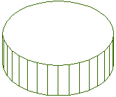
One thing AutoCAD LT is not is "lite". Apart from the fact that the moniker originally referenced AutoCAD for the LapTop, AutoCAD LT…any version…is a true 3D drawing environment.
In this illustration, at the prompt to place the Center of the circle, I entered M2P, then specified the lower right corner of room 125, then the midpoint of the opposite wall. Pretty cool.
Need proof?
- Draw a circle with a radius of 6.
- At the command line, type VPOINT and press [ENTER].
- For the view point position, type 1,-1,1 and press [ENTER].
This is like stepping away from the circle 1 step to the right, 1 step back, and 1 step up in Z.
- Double-click on the circle to open the Properties window.
- Change the Thickness to 4.
- Close the Properties window and press ESC to clear the selection.
- At the command line, type HIDE and press [ENTER].
Curiously, when you run the Hide command, a circle is displayed as an implied 3D face.
The Basics
Saving and Restoring Layer States
A named layer state is essentially a snapshot of the condition of all the layers of the current drawing at a specific point in time. You can save a layer state when all the layers are on, or when some are on and some are off, or when the layer colors are all set to Black (or White), or any number of arrangements. Here's how it works (depending upon your version).
Instructions to Save a Layer State
- Open the Layer Properties Manager and do what you need to with the layers.
Tip: It's always a good idea to create a layer state of the "original" condition of a drawing when you receive it. Especially if you are just "looking around" among the layers and will need to return to that original condition.
- In AutoCAD versions before A2005, click the Save State button. In A2005 and A2006, click the Layer States Manager button.
- In A2005+, click the New button and enter a name. In all other versions, just enter the name in the text edit box.
- Make sure all of the boxes are checked in the dialog box. All of 'em. Now click OK or Close. You have effectively captured the current layer condition and saved it by name. Cool.
To test your state, stay in the Layer Properties Manager and turn off half of the layers. Now restore the "original" layer state.
Instructions to Restore a Layer State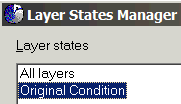
- Open the Layer Properties Manager.
- In AutoCAD versions before A2005, click the Restore State button. In A2005/A2006, click the Layer States Manager button.
- In all versions, select the name of the layer state to restore, then click the Restore button.
This is great for drawings with lots of layers and you need to quickly switch to a condition where, for example, you need to see all the topographic lines and structures, but not the construction notes. Or if you had a large floor plan and wanted to switch between the layers for the electrical plan to all the layers for the furniture plan.
 Also, please note that these layer states are by drawing only but in all versions, there is an import feature which enables you to create a .LAS file that can be imported in another drawing with a like layer collection.
Donate to CADTutor
If you found this article useful, you might like to consider making a donation. All content on this site is provided free of charge and we hope to keep it that way. However, running a site like CADTutor does cost money and you can help to improve the service and to guarantee its future by donating a small amount. We guess that you probably wouldn't miss $5.00 but it would make all the difference to us.
Note from Michael: I want to thank all of my customers for continuing to retain my training services (some for over three decades!) and let you know your donations do not go to me personally, but to the ongoing maintenance of the CADTutor ship as a whole and to support the yeoman efforts of my friend and CADTutor captain, David Watson, to whom I am grateful for this monthly opportunity to share a few AutoCAD insights.
The Basics
- Dual Dimensions in a Dim…
- UCSICON Options
- "Best of" Basics: Irreg…
- Tool Palette Basics
- Original Dimension Value
- Possible Solutions to th…
- Avoid Using 'Standard' i…
- Shorten the Plot Scales…
- Update the Source File B…
- User Increment Angles fo…
- Drawing Information
- 'Sign Language'
- Rotate with the Copy Opt…
- Use the INSERT Osnap on…
- To or From the Current L…


