

 Michael’s Corner #74
February 2009
February in the Tropics
Technically speaking, Angola is within the bounds of the Tropic of Capricorn, and that's where I'll be spending the first half of February. I'll be with a number of AutoCAD users at the Chevron facility down there and I'm really looking forward to this opportunity. It seems like Shaan Hurley was having all the travel fun there for awhile.
This month I have 3D bookends: The Visual Style referenced as ‘X-Ray’ is presented as the lead article, then in the Basics we'll take a look at the ViewCube introduced in A2009. In the Power Tool, you may want to add the SETBYLAYER command to your on-going palette and the Odd Spot looks at the wonderful command that enables you to delete those annoying layers "with nothing on them"… by Name.
For those of you interested in my specific whereabouts in Angola, here's the link using Google Maps (and if you're using Google Earth, here's the .KMZ file).
If you would like to contact me directly, you can do that also.
Blessings to one and all,
Michael
The ‘X-Ray’ Visual Style
Maybe this year I'll get my 3D course finished for my customers, but until then I've enjoyed a 3D Tutorial published by a friend of mine, Paul Wysse, P.E. (www.swissco1.com). Among a vast assortment of other wonderful 3D information was a reference to the Visual Styles palette containing an option for X-Ray Visual Style.
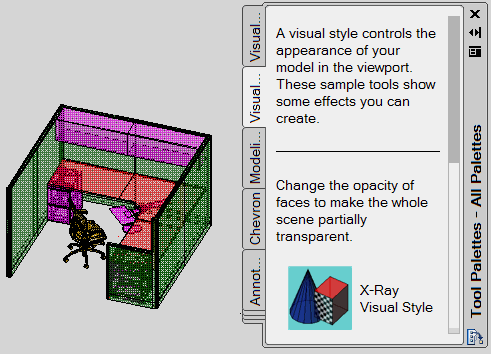
The following is a brief overview of the Visual Style itself… and will probably only serve to make you dangerous.
Precautionary Notes
Before you begin, I would recommend that you consider the following:
- Changes made in the Tool Properties dialog box for a button on the palette cannot be undone. Keep reading.
- To Export an entire palette, see Basics for May 2007.
- To Copy a button on a palette, right-click the button on the palette (such as that X-Ray Visual Style button; do it before you forget), then click Copy. Now go to your own personal palette (or on that Visual Styles palette if you prefer), then right-click in an open area and click Paste.
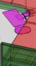
Insights to the X-Ray Visual Style
- This feature applies to any 3D object whether it is comprised of 3D Faces or is a 3D Solid. This will be of particular interest to those of you using CAP Designer (from 20-20 Technologies, Inc.) which, depending upon the vendor, provides 3D product in both categories.
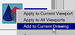
- Right-click on the X-Ray Visual Style button on the palette. To permanently include this visual style in the current drawing, click Add to Current Drawing. Now you can use the Visual Style Manager (View
 Visual StylesVisual Style Manager) to apply this style anytime.
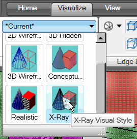
For those of you using the Ribbon, the Visual Styles pane is in the 3D Modeling Workspace, on the Visualize tab.
- Right-click the visual style button, then click Properties to open the Tool Properties dialog box. The original settings are seen in this illustration.
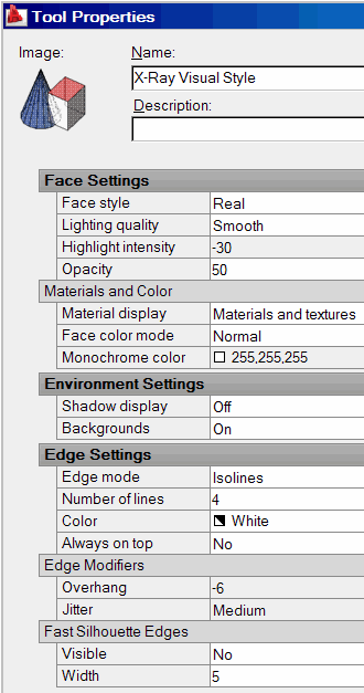
The following are some changes you may want to consider. After making the change, click OK to close Tool Properties, then click the X-Ray Visual Style button to implement the changes. If you see something you like, copy the button and rename it so you don't get confused later. Been there; did that.
Face Settings
Face Style: Gooch. Visible lines are more dominant; hidden lines recede.
Opacity: Higher number, less "see-thru". The preview image in the upper left corner of the Tool Properties dialog box will give you an idea.
Materials and Color
Face Color Mode: Desaturate. Combined with Gooch, a nice X-Ray effect. If using Tint, take a look at setting the Tint Color to ByEntity.
Edge Settings
Edge Mode: Isolines +
Number of Line: 4 +
Color: ByEntity +
Always On Top: No
Edge Modifiers
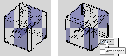
Overhang Edges button
Overhang = 6, Jitter = Off [left block]
Jitter Edges button
Overhang = -6, Jitter = Low [right block]
Power Tool
SETBYLAYER
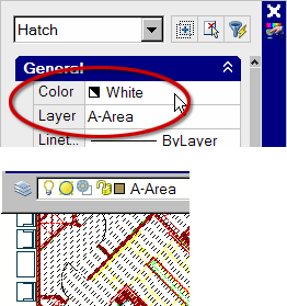
Sometimes you get drawings that are a bit confusing, mainly because the Colors of objects are not set to ByLayer.
The SETBYLAYER command automates the assignment of object properties - such as the Color - to ByLayer. In the images, you see the Hatch object has the Color property set to White.
Instructions for SETBYLAYER
- Type SETBYLAYER, then press [Enter] or go to ModifyChange to ByLayer. Since this command has no button, you may want to make a button for it. Check out the Odd Spot in April 2007.
- Select the object(s) to modify, then press [Enter]. Take the default option of
on the following prompts:
Change ByBlock to ByLayer? [Yes/No] <Yes>:
Include blocks? [Yes/No] <Yes>:
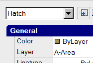
At the completion of those prompts, the properties of the selected objects will be configured to ByLayer. Works great on blocks, hatches, and dimensions.
The Odd Spot
Layer Delete ‘Name’ Option
Buried in the Format menu ![]() Layer Tools (or on the Ribbon, Home
Layer Tools (or on the Ribbon, Home ![]() Layers panel (expanded), you will eventually see the mighty Layer Delete command.
Layers panel (expanded), you will eventually see the mighty Layer Delete command.
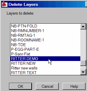
Normally used graphically, the Layer Delete command provides you the opportunity to select an object on the layer to delete. After selecting the object(s), you receive a warning, literally…
******** WARNING ********
There are 4 block definition(s) which reference the layer(s) you are deleting.
The block(s) will be redefined and the entities referencing the layer(s) will be removed from the block definition(s).
You are about to delete the following layers from this drawing.
…and then the layers are listed and you are asked if you want to continue.
But what about those times when you have no objects on those layers to select and Purge isn't doing the job either? You can always use the Name option.
Select object on layer to delete or [Name/Undo]:
This also works great if the layer to be deleted happens to be either Off or Frozen.
Note: Locked layers cannot be deleted.
The Basics
The A2009 ViewCube
Introduced in AutoCAD 2009, the ViewCube is automatically displayed when you use the 3D Modeling workspace (or use a Visual Style like this month's opening article!).
Drag it, click it, "Home" it, spin it… totally fun.
The following are the variables related to the ViewCube with their defaults and value range. All of these settings can be configured using the variables or in the ViewCube Settings dialog box.
| Variable Name | Default Value | Value Range |
|---|---|---|
| NAVVCUBEDISPLAY | 1 | 0 or 1 |
| NAVVCUBELOCATION | 0 | 0 [TR], 1 [TL], 2 [BL], 3 [BR] |
| NAVVCUBEOPACITY | 50 | 0 to 100 |
| NAVVCUBEORIENT | 1 | 0 or 1 |
| NAVVCUBESIZE | 1 | 0, 1, or 2 |
Insights to the ViewCube
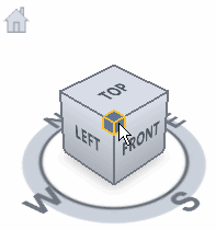
- All the edges, corners, and faces of the ViewCube can be selected as view positions.
- Any edge, corner, or face can be clicked and dragged, similar to the 3D Orbit feature.
- Click the N, S, W, or E letters to take a view from that direction; similar to clicking Left, Front, Right, or Back.
- Click and drag one of the letters and the ViewCube will turn like a lazy-susan. You can really only get a 1/4 turn out of each one, but you can eventually go all the way around.
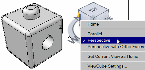
- Right-click the ViewCube for a shortcut menu, including access to the ViewCube Settings dialog box.
Left Field
Skyline Chili (www.skylinechili.com) - From the mind of a young boy in a small kitchen in Kastoria, Greece, Skyline Chili now operates in four states, annually serving up nearly 1 million gallons of chili, 3 million pounds of cooked pasta and 20 million cheese coneys, using more than 165 million pounds of Wisconsin cheddar cheese. Yes, this is my favorite when I come home after a road trip.
Donate to CADTutor
If you found this article useful, you might like to consider making a donation. All content on this site is provided free of charge and we hope to keep it that way. However, running a site like CADTutor does cost money and you can help to improve the service and to guarantee its future by donating a small amount. We guess that you probably wouldn't miss $5.00 but it would make all the difference to us.
Note from Michael: I want to thank all of my customers for continuing to retain my training services (some for over three decades!) and let you know your donations do not go to me personally, but to the ongoing maintenance of the CADTutor ship as a whole and to support the yeoman efforts of my friend and CADTutor captain, David Watson, to whom I am grateful for this monthly opportunity to share a few AutoCAD insights.
Share this page:


The Basics
- Dual Dimensions in a Dim…
- UCSICON Options
- "Best of" Basics: Irreg…
- Tool Palette Basics
- Original Dimension Value
- Possible Solutions to th…
- Avoid Using 'Standard' i…
- Shorten the Plot Scales…
- Update the Source File B…
- User Increment Angles fo…
- Drawing Information
- 'Sign Language'
- Rotate with the Copy Opt…
- Use the INSERT Osnap on…
- To or From the Current L…


