

 Michael’s Corner #77
May 2009
Discoveries and Recoveries
The discovery this month is a result of an email I received on the day I was writing this article and it had to do with taking X,Y data points that were in Excel, then getting them to create a drawing. Take a look at the Odd Spot for that one. As for the recovery, Workspaces have been around for several versions and I'm just now getting to their coverage, so thank you for your patience on that one.
This month's Power Tool is a long one since it involves a Dynamic Block… but I had a really great time making a video for you to replay! And there's a reminder in Basics about the Taskbar variable; not something I use, but you may be interested in it if your more of a mouse person, than a hot key person.
Spring seems to be taking its good ole time getting around the corner here in Kentucky, but I get to spend some quality on the riding mower.
If you would like to contact me directly, you can do that also.
Blessings to one and all,
Michael
Workspaces circa AutoCAD 2010
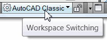 The Workspace feature has been around since A2006 and although I have trained on it, this is the first time I have written about it; my apologies. Workspace definition (per the Help menu): Workspaces are sets of menus, toolbars, palettes, and ribbon control panels that are grouped and organized so that you can work in a custom, task-oriented drawing environment. (In this image from AutoCAD 2010, I like how they've added the name of the current workspace beside the Workspace Switching icon on the status bar.)
Ribbon Note: The Workspace named 2D Drafting and Annotation provides several Ribbon panels and tabs containing common features needed for 2D drawings. The Workspace named 3D Modeling provides 3D-related features on the Ribbon. Both of these are good starting points, then you can refine the Ribbon a bit more, then saved it as another Workspace.
Cautionary note: I would first create a workspace of your current menu, toolbar, etc. arrangement so you can return to that condition when we're finished ‘experimenting’.
The following procedure has been used on A2008, A2009, and A2010. If you have A2006 or A2007, there may be slight differences, but the idea is the same.
Instructions to Create a Workspace
-
To save your current workspace by name in:
 A2008, go to the Tools menu, then click Workspaces
 Save Current As. Enter a name for the current workspace, then click Save.
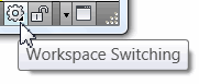
A2009/A2010, click the Workspace Switching icon on the right half of the status bar, then click Save Current As. Enter a name for the current workspace, then click Save.
Note: In A2008, you may find the Workspaces toolbar helpful in making your selection(s).
-
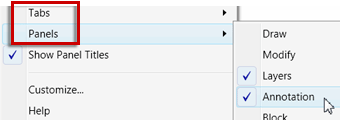 Now, configure the position of your toolbars (or the panels and tabs of your Ribbon) to suit your way of working. To turn off panels or tabs on the Ribbon, right click on any panel and you see an item for Tabs, as well as Panels.
When I was training the folks in Angola on A2008 (which doesn't have the Ribbon), we made a workspace with 2D-related toolbars and one with 3D-related toolbars.
Repeat Step 1 for your respective version, then save the workspace as CT-May09.
To test your workspace, set some other workspace to be current, such as 2D Drafting & Annotation – in A2008 from the Workspaces toolbar, or in A2009/A2010 from the Workspace Switching icon on the status bar.
Now select your newly created workspace and you should be good to go!
Bonus Points…
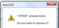 If you want to make changes to your Workspace, configure your toolbars/Ribbon first, then use Save Current As and choose the name of the workspace to be replaced from the dropdown list.
- To delete a Workspace from the list, open the CUI, then expand the workspaces node, then use the right-click menu on the workspace to delete.
Power Tool
Dynamic Block Feature: Move + Stretch
 There are a lot of Dynamic Block samples on the Tool Palettes, but sometimes I just want to know how to make my own, (thereby enabling me to more accurately edit existing ones).
Here are the instructions on creating a dynamic block that moves the text, while stretching the block geometry. Click here to go to the AutoCAD Stuff page of my website where you can download the DynaDoor and DynaLabel drawings. Insert those into any drawing and they are good to go. For my initial coverage of the dynamic block feature, take a look at the lead article of Michael's Corner, July 2006 to learn how to add multiple visibility parameters to a dynamic block.
Tip: For those of you with a block source drawing containing blocks for your tool palette, insert these dynamic block drawings into that source file, save it, then drag them onto your tool palette. See Michael's Corner, Basics, March 2006 for more information on the importance of the block source drawing for tool palette blocks.
Instructions to Create a Dynamic Block Combining Move & Stretch Actions
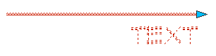
- In Model Space, draw a polyline with a Width of 1/16″ that is 8″ long.
- Add a text object (Dtext or Mtext) with a Height of 1/2″, below and aligned with the end of the line.
- Launch the Block command, and check the box and the bottom to Open in Block Editor.
- Enter a Name for the block (I'm calling mine DynaLine), Select the objects, specify the left endpoint as the Basepoint, then click OK to open the Block Editor.
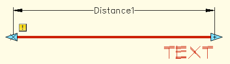
- On the Parameters tab of the Block Authoring Palettes, click Linear Parameter, then accurately snap to the left endpoint, then the right endpoint of the polyline. Place the Distance label above the line, just like you would a dimension line.
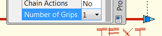
- Select the Distance label, then open Properties. Scroll down and change the Number of Grips value to 1. This setting will result in one parameter (cyan arrowhead) on the right endpoint of the line. You can now close the Properties window.
- On the Actions tab, click Move Action.
- When prompted to select the parameter, click the cyan parameter at the right end of the line. A red circle and X appear on that parameter.
- Press [Enter] to accept the default parameter association of <Second>.
- When prompted to select the objects for the Move action, select the text, then press [Enter].
- Prior to A2010, you are prompted to position the yellow lightning bolt icon. Turn off Ortho (the icon moves erratically if you don't),then place the icon off to the side anywhere. In A2010, the (more elegant) action icon is automatically placed off to the right.
- On the Actions tab, click Stretch Action.
- When prompted to select parameter, click the same cyan parameter, then press [Enter] to accept the default parameter association of <Second>.
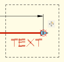 Specify two corners of the Stretch frame, similar to what you see here.
- When prompted to select objects for the stretch, click anywhere on the polyline, then press [Enter]. The text object is already associated with the parameter from the previous steps.
- Prior to A2010, you are prompted to position the yellow lightning bolt icon. Position the icon anywhere off to the side; if you're using A2010, it is automatically placed for you.
- Click Close Block Editor, save your changes, then click on the block to display the stretch parameter icon. When you click it, you have enabled the stretch action… and the text moves with it!
The Odd Spot
Coordinates from Excel into AutoCAD
 I received an email from a friend of mine at Nicholson Construction asking if there was an easy way of taking coordinates out of Excel and creating a drawing from those values, rather than inputting them, one set at a time. Yes, actually, there is… and it is amazingly simple if we create a script (.SCR) file.
Prerequisite: The X and Y values need to be in a single cell in the format of X,Y for this to work. If X and Y have their own column, you will need to make the necessary adjustments to get them to X,Y format.
Instructions to Create a Drawing with X,Y Coordinates from Excel
- In Excel, highlight and Copy the column of X,Y coordinates to be used to generate the drawing.
- Open Windows Notepad (StartAll ProgramsAccessoriesNotepad).
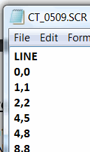
- Before pasting the coordinates, type LINE as the first word in the file (this will launch the Line command when the script is run), then press [Enter].
- Now Paste the column of coordinates into the file and you should see something like that shown in the figure.
- Close and save the .SCR file (remember where you're saving it).
- In AutoCAD, launch the SCRIPT command, then navigate to where you saved your file in the previous step, then select it and click Open. AutoCAD will launch the Line command then, beginning at the first set of coordinates entered, will draw line segments from one point to the next.
You may also want to consider…
- Replacing the LINE command with the PLINE command.
- Adding the word CLOSE as the last word in the script to have the linework close back to the start point.
- Dragging the .SCR file out of Windows Explorer and dropping it into the drawing window.
The Basics
Separate Drawings on the Taskbar
By default, when you have AutoCAD open, you see one AutoCAD icon on the Windows taskbar, regardless of how many drawings you have open, as you see in this first image.
For those of you who want to see icons displayed along the Windows taskbar for all the drawings you have open, you will be happy to know the AutoCAD variable of… well, Taskbar… can make that happen.
Set the TASKBAR variable to <1>, then, when you have more than one drawing open, you will see an icon for each of the open drawings.
Left Field
A Bit of Bar-B-Q Trivia: During the 1940s and early 1950s, George Stephen worked for Weber Brothers Metal Works, outside Chicago where he gained experience in shaping and fabricating metal parts, including dome-shaped buoys for use out on Lake Michigan. An avid barbecuer, he became increasingly frustrated with the uneven and uncontrollable flame of the open brazier grill he used at home. While at work, his grilling experience merged with his skills as a metal worker. "We were making dome shapes at the shop," Stephen once said. "I took one of the domes, drilled some holes in the bottom and lid, welded supports to hold two wire grates, and gave my strange looking kettle-shaped grill a try. It worked great." So began the storied and far-reaching history of the Weber Grill. www.weber.com
Donate to CADTutor
If you found this article useful, you might like to consider making a donation. All content on this site is provided free of charge and we hope to keep it that way. However, running a site like CADTutor does cost money and you can help to improve the service and to guarantee its future by donating a small amount. We guess that you probably wouldn't miss $5.00 but it would make all the difference to us.
Note from Michael: I want to thank all of my customers for continuing to retain my training services (some for over three decades!) and let you know your donations do not go to me personally, but to the ongoing maintenance of the CADTutor ship as a whole and to support the yeoman efforts of my friend and CADTutor captain, David Watson, to whom I am grateful for this monthly opportunity to share a few AutoCAD insights.
Share this page:


The Basics
- Dual Dimensions in a Dim…
- UCSICON Options
- "Best of" Basics: Irreg…
- Tool Palette Basics
- Original Dimension Value
- Possible Solutions to th…
- Avoid Using 'Standard' i…
- Shorten the Plot Scales…
- Update the Source File B…
- User Increment Angles fo…
- Drawing Information
- 'Sign Language'
- Rotate with the Copy Opt…
- Use the INSERT Osnap on…
- To or From the Current L…


