

Modifying Objects
Introduction
Modification of objects is at the heart of 3D modelling. Once geometry has been created using the most appropriate method (AutoCAD 2D, Standard Primitives, Shapes etc) then the modeller will start the modification process. Modification differs from transformation in that it is the geometry itself that is edited and changed
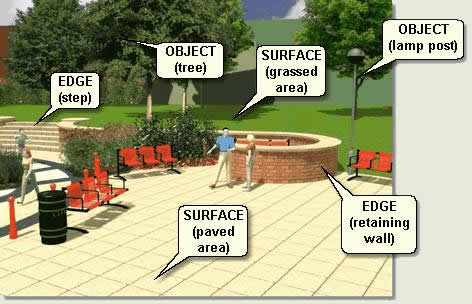
Infrastructure and landscape modelling mainly consists of surface modelling and object modelling, with edges being dealt with by simple extrusions or lofts.
'Surfaces' in this context means the distinct landscape surface matrix of roads, paths, pavements, planting beds and other hard and soft surface elements. These are modelled using meshes and are created and modified in a number of ways. 'Objects' in this context are those elements such as bollards, litter bins, seating, shelters, people, trees etc that occupy the landscape and usually sit on top of surfaces. These, again, are modelled using meshes that have been created and modified in a number of ways. Each element relies on effective knowledge of spline modelling, and creation and manipulation of meshes together with knowledge of which creation method to use and the range of appropriate modifiers to use
MAX / VIZ contains powerful modification tools that can be categorised thus:
Sub-Object Editing
Basic Parameters
Modifiers and The Stack
Download Sample Data
kf204_files.zip (796kb)
module_2_maps.zip (5.9mb)
Sub-Object Editing
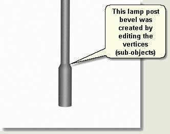
To understand how modifications are performed you need to understand what objects are made of. Key Fundamentals firstly explores what comprise objects and the hierarchy of sub-objects
A sub-object is a subset of an object's geometry. Many objects have various types of sub-objects that you can work with independently. For example, an editable mesh object's sub-objects are vertices, edges, faces, polygons, and elements. At the sub-object level you can select sub-objects, transform the selections, apply modifiers, and so on
The following sub sections explain the fundamental processes involved in sub-object editing:
Sub-Object Hierarchy
Spline Editing
Mesh Editing
Sub-Object Hierarchy
In this section the sub-objects that you will need to manipulate for landscape work are explored
Spline Sub-Objects
- Open kf204_01.max. This scene contains a simple box and two lines
- Select Line01
- Tools menu > Isolate Selection
- Modify Panel > In the Stack Window click on the + sign to expand the sub-objects under Line
- Select Vertex from the list of sub-objects. This is at the top of the list because it is the simplest sub-object (ie one point)
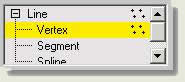
- Alternatively press the Vertex Button
![]()
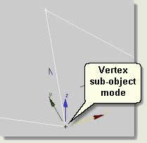
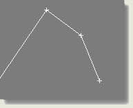
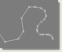
Note that in the viewport a small cross is displayed at each vertex on the line. You are now in vertex sub-object mode. This means that you can edit the vertices on their own. When in this mode you cannot select other objects
In the viewport select a vertex or vertices and notice that it/they turn red. Use the Transfom Gizmo to move vertices around
- Click on either the yellow Vertex line in the Stack Window or on the Vertex Button to exit sub-object mode
TIP: The Navigation Tools Arc Rotate button flyout includes an Arc Rotate Sub-Object button ![]() which enables you to Arc Rotate around any selected sub-objects. This is an invaluable aid when modelling at sub-object level
which enables you to Arc Rotate around any selected sub-objects. This is an invaluable aid when modelling at sub-object level
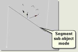
- Select Segment from the list of sub-objects. This is next down the list because it is the next less simple sub-object (ie a line joining two points). Alternatively press the Segment button
- You are now in Segment Sub-Object Mode. In the viewport select a segment and it turns red. Use the Transfom Gizmo to move segments around
Attaching
To demonstrate the spline sub-object mode you will need to add another line to Line01. Attaching is the process of converting two objects into one and is used extensively to create objects using multiple elements that have been modelled separately. These elements or 'parts' are 'attached' and given certain identifiers (Material IDs,for example, dealt with later) so that different materials, for example, are assigned to different parts of the object
- Exit segment sub-object mode
- Exit Isolation. Zoom to the two lines in the viewport and select Line01
- Modify Panel > Geometry rollout > Attach. The Attach button turns orange and you can attach objects to the selected line
- In the viewport place the cursor over Line02. The cursor changes to the Attach Cursor. Left click to attach Line02 to Line 01
NOTE: The name of the combined object keeps the name of the original object. Also, as explained later, other properties of the original object are passed to the attached object such as an editable spline rather than a line object
- Select Line01.This now comprises two lines that have been attached
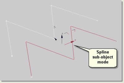
- Select Spline from the list of sub-objects. This is at the bottom of the list because it is the less simple sub-object (ie spline made of multiple segments and vertices)
- You are now in Spline Sub-Object Mode. In the viewport select one of the splines and it turns red. Use the Transfom Gizmo to move the two splines around
- Exit spline sub-object mode
Mesh Sub-Objects
- Select Box01
- Tools menu > Isolate Selection
- Right click over the selected box to display the right click menu:
- Right click menu > Convert To: > Convert to Editable Mesh. This converts the box object to a mesh that is editable (ie you can access the sub-objects). Notice that the object is listed as 'Editable Mesh' in the Stack Window
- Modify Panel > In the Stack Window click on the + sign to expand the sub-objects under Editable Mesh
- Select Vertex from the list of sub-objects. This is at the top of the list because it is the simplest sub-object (ie one point)
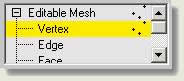
- Alternatively press the Vertex Button
![]()
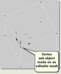
Note that in the viewport a small blue dot is displayed at each vertex on the mesh. You are now in vertex sub-object mode. Again, this means that you can edit the vertices on their own and when in this mode you cannot select other objects
- In the viewport select a vertex or vertices and notice that it/they turn red. Use the Transfom Gizmo to move vertices around
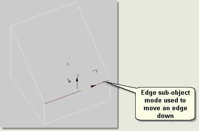
- Select Edge from the list of sub-objects. This is next down the list because it is the next less simple sub-object (ie a line joining two points). Alternatively press the Edge button
- You are now in Edge Sub-Object Mode. In the viewport select an edge and it turns red. Use the Transfom Gizmo to move edges around
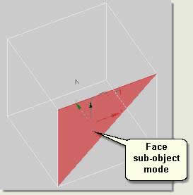
- Select Face from the list of sub-objects. This is next down the list because it is the next less simple sub-object (ie a face joining three points). Alternatively press the Face button
- You are now in Face Sub-Object Mode. In the viewport select a face and it turns red (Shade Selected Faces has been turned on in the Viewport Configuration dialog). Use the Transfom Gizmo to move faces around
TIP: On the Selection rollout check Ignore Backfacing if you just want to select those faces facing you in the viewport. Also note that Force 2-Sided needs turning off for this to take effect
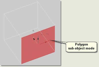
- Select Polygon from the list of sub-objects. This is next down the list because it is the next less simple sub-object (ie face on the same plane). Alternatively press the Polygon button
- You are now in Polygon Sub-Object Mode. In the viewport select a face and it turns red (Shade Selected Faces has been turned on in the Viewport Configuration dialog). Use the Transfom Gizmo to move polygons around
- Exit Isolation
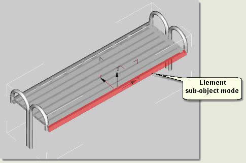
- Open Element Sub Object.max. This scene contains a bench to illustrate Element sub-object mode
- Select Bench
- Enter element sub-object mode
- In the viewport select elements of the bench
- Exit element sub-object mode
TIP: Often when first learing about sub-objects the user will leave an object in sub-object mode and hence will not be able to select any other objects. When this confusion occurs check that you have not left an object in sub-object mode
Spline Editing
Spline editing is an essential part of landscape modelling as it is used extensively in the creation of surfaces and lofts used for edging. Splines are also edited as part of creating boolean and shapemerge compound objects and in modifiers such as the Bevel Profile modifier. In general you need a good all-round knowledge of the tools available for and process of spline editing
NOTE: The availability of functions on the rollouts on the Modify Panel change depending which sub-object level you are in. Functions for vertices, for example, are different than those for segments. If a function is not relevant for a particular sub-object, the part of the interface will be greyed out
Convert to Editable Spline
- Create a shape such as a rectangle. Notice that the parameters in the Modify Panel are parametric
- Place the cursor over the shape and right click
- Right click menu > Convert To: > Convert to Editable Spline. Notice that the text in the Modify Stack window changes to Editable Spline
This is the quickest way to covert a shape to an editable spline
NOTE: Once you have changed a shape to an editable spline you cannot access the shape's parameters again
All the following commands are available on the Modify Panel rollouts. Select each sub-object mode accordingly
Global parameters
Make Renderable
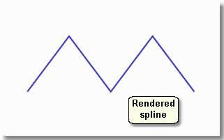
- Open kf204_02.max. This scene contains an editable spline
- Select Line01
- Render the viewport. Notice that the line is not rendered
- Rendering rollout
- Check Renderable, Thickness: 01, Sides: 6
- Render the viewport. The spline is rendered
- Change the thickness a few times and test render
- Keep this scene open for the next operations on vertices
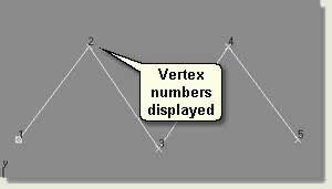
Show Vertex Numbers
- Selection rollout / Display group box
- Check Show Vertex Numbers. This displays the vettex numbers the viewports and is useful for spline sub-object editing to show the direction in which a line has been drawn. The direction a line has been drawn has implications in the creation of surfaces using the surfacing modifiers (explained later) and to see the effect of reversing splines (below)
Interpolation
- Interpolation rollout
- Increase the Steps to give a smoother line around curves - use in the following routines on curved lines
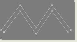
Vertex sub-object editing
- For all of the following operations enter Vertex Sub-Object mode after selecting Line01 and open the Geometry rollout
Change Vertex Type
- In the Top viewport select the bottom middle vertex
- Right click over the selected vertex to display the right click menu. Notice that the vertex type is Corner
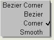
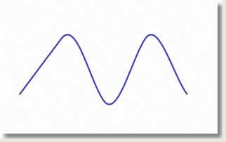
- Select Smooth from the four options. Notice the line changes to reflect the new vertex type
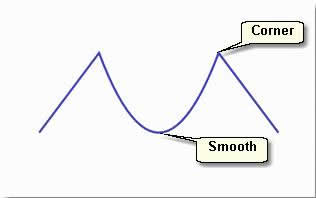
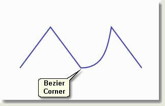
- Select Corner (to return to the original spline shape) and then Bezier Corner. This gives you two handles that follow the in and out path of the spline through the vertex. Move one of the yellow handles to curve one of the spline paths thus:
TIP: Changing the vertex back to corner is good practice. If a vertex is changed to Bezier, for example, and edited then changed to Bezier Corner, it will inherit properties of the Bezier vertex
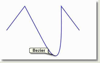
- Select Corner again and then Bezier. This gives you two handles that affect the in and out paths of the spline through the vertex. Move these handles to change the line of the curve
TIP: Change the Interpolation steps of the spline on the Interpolation rollout to increase the smoothness of any curves
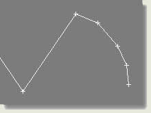
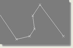
- Select multiple vertices and change the vertex type thus:
Add Vertices
- Open kf204_02.max again and enter vertex sub-object mode for Line01
- Refine
- Place the cursor over one of the line segments and click to add three vertices
- Move the vertices to new positions
- Right click to exit the command
Weld Vertices
- Select the three new vertices
- Weld. The vertices do not weld (join together to become one vertex)
- Adjust the Weld threshold spinner to 2
- Press Weld again. The three vertices are converted to one vertex
This is useful to reduce detail on a spline that has too many vertices
Insert Vertices
- Insert
- Place the cursor anywhere on the spline and click and drag to insert vertices and add to the spline
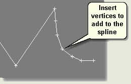
- Right click to exit the command
Delete Vertices
- Simply select vertices and press Delete on the keyboard
- Delete, add, move, weld, insert and change types of vertices to gain any required result
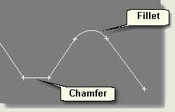
Fillet / Chamfer
- Select one vertex between two vertices
- Fillet
- Type in or use the spinner (spinner snap on and set to correct precision) to fillet the vertex to the required amount
TIP: This is a 'one-off' operation. To experiment with fillets and chamfers use Undo to remove the fillet or chamfer before trying another value
- Select another vertex
- Chamfer
- Type in or use the spinner to chamfer the vertex to the required amount
Segment sub-object editing
- For all of the following operations enter Segment Sub-Object mode after selecting Line01 and open the Geometry rollout
Add Segments
- Open kf204_02.max
- Select one of the segments
- Refine
- Position the cursor over any part of the line (the cursor changes) and insert a new segment break
- Right click to exit the command
- Select one of the segments and move to a new position
- Select another segment
- In the spinner box to the right of the Divide button type 3
- Divide This divides the segment into three equal segments
Insert Segments
- Insert
- Place the cursor anywhere on the spline and click and drag to insert segments and add to the spline
Delete Segments
- Simply select a segment and press Delete on the keyboard. Note that, unlike deleting vertices this takes a complete segment out of the spline
Divide Segments
- Open kf204_02.max again
- Select one of the segments
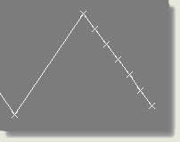
- Next to the Divide button type 5 in the spinner box
- Divide
- The segment is divided equally into 5 segments
- Select more than one segment and repeat. Each segment is divided by the specified amount
This is useful to add uniform detail to a spline
Detach Segments
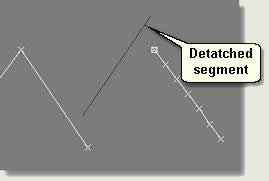
- Select a segment
- Detach
- Rename the detached segment on the Detach dialog. Press OK. The segment is detached from the spline
- Move the detached segment
- Repeat, only this time check Copy before detaching. This creates a copy and keeps the segment in the original spline
NOTE: Detaching is the effectively the opposite of Attaching
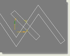
Spline sub-object editing
For all of the following operations enter Spline Sub-Object mode after selecting Line01 and open the Geometry rollout
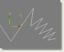
Create Lines
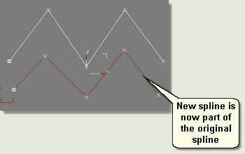
- Select the spline
- Create Line
- Draw another spline in the Top viewport. This becomes part of the selected spline
- Right click to exit the command
- Select the new spline to show that it is part of the original spline
Attach Splines
- Exit sub-object mode and draw another separate line object
- Select the original Line01
- Attach
- Select the new line. This is attached to the original line making one object
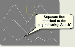
NOTE: A common mistake is to keep in the Attach Command and inadvertantly attach more objects. Always make sure you exit from the Attach Command when finished attaching
Insert Splines
- Insert
- Left click on a point over the spline and extend the spline by left clicking and dragging
Reverse
- Selection rollout / Display group box / Check Show Vertex Numbers
- Geometry rollout / Reverse. Notice that the vertex numbers along the spline are reversed each time you press this button. This technique is most useful for reversing splines that are used to create surfaces using the surface modifiers
Outline
- Type 0.5 in the spinner box next to the Outline button
- Outline
- The line is given an outline to the specified value
- Press Undo
- Type 0.7 in the spinner box next to the Outline button and check Centre
- Outline
- This produces and outline of 0.7 and this time centres the operation on the line
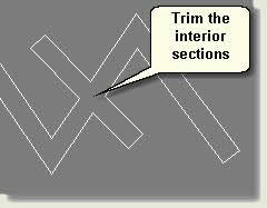
Trim Splines
- Using the same scene create another line crossing the original line and give it an outline of 0.7
- Attach the new line to the original to make one object
- In spline sub-object mode select the original spline
- Trim
- Select all the interior sections of the spline one by one to trim the interior of the spline
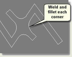
- Finally go to vertex sub-object mode, weld the vertices where the lines have been trimmed (at the trim point there seems to be one vertex, however, there are 2). Then fillet each corner to produce the following spline
Delete Splines
- Simply select a spline and press Delete on the keyboard
Close Splines
- Create any open line
- Close. This closes the line
Detach Splines
- Create one editable line from two splines by using Attach
- Select one spline sub-object
- Detach. Either detach the spline completely or use the Copy checkbox to create a copy and leave the original spline in place
Mesh Editing
Mesh editing, like spline editing is an essential part of landscape modelling. It is used extensively in the modification of surfaces and objects and is usually undertaken after basic parameters and modifiers have been used
Convert to Editable Mesh
- Create a Standard Primitive such as a box. Notice that the parameters in the Modify Panel are parametric
- Place the cursor over the box and right click
- Right click menu > Convert To: > Convert to Editable Mesh. Notice that the text in the Modify Stack window changes to Editable Mesh
This is the quickest way to covert any geometry to an editable mesh
NOTE: Once you have changed geometry to an editable mesh you cannot access any parameters again
TIP: If you are undecided whether or not to convert to an editable mesh use an Edit Mesh modifier to edit the geometry. Then convert to editable mesh at the appropriate time
- All the following commands are available on the Modify Panel rollouts. Select each sub-object mode accordingly
Vertex sub-object editing
Soft Selection
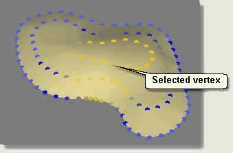
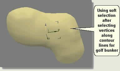
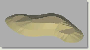
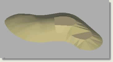
- Open kf204_03.max. This scene contains a terrain object that has been converted to an editable mesh
- Select one of the vertices at the top of the terrain
- Soft Selection rollout > check Use Soft Selection. In the User viewport notice that the selected vertex is red and that vertices radiating from that point go from orange to yellow the further they are from the selected vertex
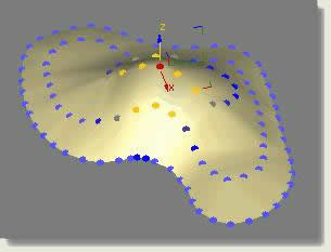
- Adjust Falloff to increase or decrease the area affected by soft selection
- Adjust Pinch and Bubble to change the accuteness of selection if needed
- Move the vertex up on the Z axis and notice that other vertices move. The nearer the selected vertex, the more they move in accordance with the selected vertex
TIP: Make sure that no edge vertices are selected if you want the edges to stay where they are. Vertex sub-object alignment, however, can be used afterwards to re-seat the edge vertices
TIP: For more uniform soft selection on terrains use the polygon selection method (selected method button flyout) to select a number of vertices following a contour
Weld Vertices
- Select all the vertices following the top contour
- Weld
- Adjust the Weld Threshold up to abou 15 and keep selecting and welding until one vertex remains
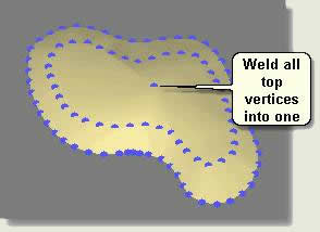
This is useful to remove selected detail from a mesh
Edge sub-object editing
Select Open Edges
- Select Open Edges
- Using Transform Type-in dialog Offset move the selected open edges down -4.0
- Exit sub-object mode and move the terrain up 4
This is useful to give rounded 'relief' to planting beds for example
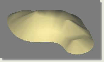
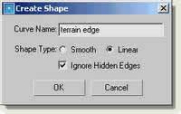
Create Shape from Edges
- Select Open Edges
- Create Shape from Edges
- On the Create Shape dialog check Linear and rename 'terrain edge'. Press OK
- Exit sub-object mode and select terrain edge
- Modify Panel > Extrude. Uncheck Cap Start and Cap End
- Extrude the terrain edge down to create an edge to the terrain
This is useful to give flat 'relief' to a terrain (woodland block for example)
Face sub-object editing
Ignore Backfacing
- Open kf204_04.max. This scene contains an Ngon that has been extruded and converted to and editable mesh. Shade Selected Faces has been checked in the Viewport Configuration dialog and Force 2-Sided has been turned off
- Face sub-object mode
- Selection rollout > check Ignore Backfacing
- In the User viewport select a number of faces and then Arc Rotate around the object. Notice that any face that was not facing the view was not selected
NOTE: Ignore Backfacing will not work if Force 2-Sided is checked on in the viewports
This is a useful selection method for sub-objects (applies to all sub-objects)
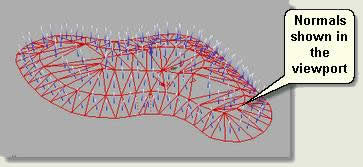
Show Normals
A normal is a vector that defines which way a face is pointing. The direction of the normal indicates the front, or outer surface of the face. You can show normals for selected faces by doing the following:
- Open kf204_03.max
- In the User viewport uncheck Shade Selected Faces
- Select all the faces. The edges of the faces turn red when selected
- Selection rollout > check Show Normals. Change the Scale to 1.5
- Select all the faces. The normals are shown in the viewport
- Surface Properties rollout > Normals > Flip. This flips the normals as can be seen in the viewport
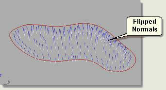
TIP: When faces seem to be missing, often when geometry is imported from other programs, this is often due to the normals on some faces being the wrong way round. Use face sub-object mode to select faces and then Unify and Flip to correct this situation. A global solution would be to check Force 2-Sided, however efficient modellers do correct the root cause. Also note that the Render Scene dialog has an option to Force 2-Sided as the issue also has to be addressed in the output render (ie the faces may be displayed in the viewport due to Force 2-Sided being checked on for viewport configuration, but the render settings may have it checked off)
Divide Faces
- Divide
- In the Top viewport left click in the centre of faces to split the face into three regular faces
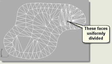
This divides faces in a regular fashion
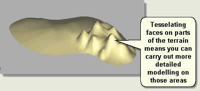
Tesselate Faces
- Select a number of faces
- Tesselate. The selected faces are split up into more numerous faces
- Tesselate again
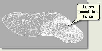
This adds detail to the mesh so that more detailed modeling can take place on those areas
Smoothing
Key Fundamentals does not cover smoothing techniques, however, for information this exercise shows what smoothing does
- Open kf204_03.max again
- Select all faces in the User viewport, smooth and highlight display mode
- Surface Properties rollout > Smoothing Groups > Clear All
- Select half of the faces then press the 1 button. This means that all these faces share the smoothing group 1 and are all smoothed together
Therefore, if a face shares the same smoothing group number as the face next to it then the join between the faces will be smoothed in the display and output renders
Polygon sub-object editing
Extrude / Bevel Polygons
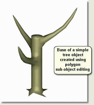
To make the base for a simple tree:
- Open kf204_04.max
- Polygon sub-object mode. Select one of the polygons on the side of the extruded pentagon. The extrusion was given a number of segments to facilitate this
- Extrude. Use the spinner (spinner snap on) to extrude the polygon as below
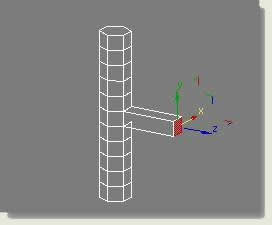
- Move the polgyon up slightly to make the branch angle go upwards
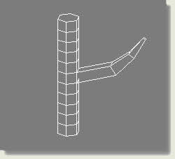
- Bevel. Bring the Bevel Spinner down slightly, bevelling the polygon inwards to taper the branch
- Change the Reference Coordinate System to Local. This alters the transform gizmo to act on the selected polygon (switch between Local and View to see how the gizmo changes)
- Rotate the polygon round the X axis to angle the next extrusion further upwards
- Repeat the extrusion and bevel twice more to create a main branch of the tree making sure that when moving the polygon up you are in the View Reference Coordinate System and when rotating the polygon you are in the Local Reference Coordinate System
- Repeat the process for two more branches round the trunk. Finally, apply a MeshSmooth modifier to the tree base to smooth the trunk and branches:
- Modify Panel > MeshSmooth modifier
- Subdivision rollout > set the Iterations to 1
- Right click over the object and Convert To Editable Mesh
TIP: When finished modelling an object always convert it to an editable mesh, unless you may need to revisit and modify some of the parameters in the Modify Stack later
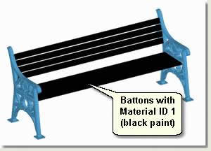
Element sub-object editing
Edit Material IDs
The different parts of landscape objects such as the seat and legs of a bench or column and luminaire of a lighting column, for example, are modelled separately and then 'attached' using the Attach sub-object command. These parts then form one object. The parts are called 'element' sub objects. You can access the elements to re-position or most often to change the material ID on the element so that it will 'pick up' a material in a multi / sub-object material that has been applied to the object
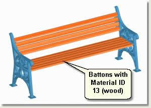
- Open kf204_05.max. This scene contains a bench that has a multi / sub-object material assigned to it
- Polygon subWindow select the seat battons
- Element sub-object mode
- Window select all the wood seat battons
- Surface Properties rollout / Material group box / ID Use the spinner to change the ID number down and then up again. Notice that the material on the seat battons changes accordingly. They are picking up on different sub materials (in this case blue paint or wood). Look in the material editor to reference the particular sub materials in the material ('1' being wood and '2' being blue paint) Note: the image below shows a different seat and different ID numbers from our example scene
Basic Parameters
Think of basic parameters as the ability to change the initial geometry at the creation stage. Modification can be carried out when the object is being created, however, the most effective way to modify an object is to create it with arbitrary parameters and then immediately open the Modify Panel to type in the correct parameters or edit the geometry in Sub-Object Mode
How you envisage the design of a particular landscape element (surface, edge or object) will change will dictate how you manage its basic parameters. Re-visit 1 Options for Creating Objects and think about how you would want to modify these elements, if at all. Examples are as follows:
AutoCAD 2D
Delete and re-import contour lines that have been changed in AutoCAD
Delete and re-import road surface boundary and surrounding surface boundaries that have been changed in AutoCAD
Delete and re-import blocks for bollard positions that have been changed in AutoCAD
Reference 2D splines for wall elevations and extrude. Change the 2D splines and these will be referenced in the 3D wall
Standard Primitives
Change the amount of height segments on a cylinder used for the basic geometry of a bicycle stand. The stand has a Bend Modifier applied and increasing the amount of segments of the initial cylinder makes a smoother bend
Instance a column or fence post so that you can change the parameters such as height or width globally
Shapes
Use a spline as the Shape operand of a loft. Change the geometry of the shape and this is reflected in the loft
Reference a shape and use as part of other geometry. Change the shape parameters and these will be referenced in the 3D model
Use a parametrical shape as part of a Loft Compound Object. Change the shape parameters and these will be passed on to the loft
Compound Objects
Instance the subtraction operand for a subtraction Boolean Compound Object. Change the subtracted operand geometry to see the changes reflected in the Compound Object
Instance the Shape used for ShapeMerge Compound Object. Change the shape to see the changes reflected in the ShapeMerge
Instance the contour lines used to create a Terrain Compound Object. Select the original contours and edit to see the changes reflected in the Terrain
Instance a simple 3D tree (created by applying modifiers to a sphere) distribution object as part of a Scatter Compound Object. Change the parameters of the modifiers on the sphere to see the cahnges take effect on all the Scattered trees
Use a shape as part of a Loft Compound Object. Change the shape parameters and these will be passed on to the loft
Make a list of possible changes you may want to make to basic objects used for the start of the modelling process and for what purpose
Make a list of element that you would not want to change and why
Modifiers and The Stack
MAX / VIZ modifiers are extremely useful for changing an object's geometry quickly and accurately and in numerous different ways depending on the required result. Modifiers are usually used after altering the basic parameters of objects to optimaise them for modification. The following example shows how modifiers are applied and how you can re-visit the parameters of particular modifiers in the Modifier Stack to create different effects
NOTE: Refer to MAX / VIZ User Reference to explore the Modifier Stack Functionality further. Key Fundamentals introduces you to the basic process of working with Modifiers and The Stack
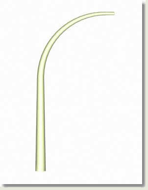
- Reset MAX / VIZ. This example shows the modification of a simple cylinder to form the main section of a lamp post
- Create a cylinder: Radius: 0.5, Height: 20, Height Segments: 8, Sides: 12
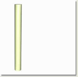
- Modify Panel > Modifier List > Taper > Parameters rollout > Taper > Amount: -0.5
- Modify Panel > Modifier List > Bend > Parameters rollout > Bend > Angle: 90
- The Modifier Stack contains the cylinder and above this the Taper Modifier - and then the Bend Modifier
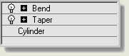
NOTE: The + sign at the left of the modifier text gives acces to the 'Sub Objects' of the modifiers. Often these are a 'gizmo' that allows you to transform the position of the modifier on the object in the viewport and a 'Centre' that allows you to move the centre of the modifier on the object in the viewport
This is the order in which MAX / VIZ applies the changes to the object. You will now alter parameters at each stage of modification to produce the required result
- Make sure that the Show end result on/off toggle
 is deppresed. This enables you to see the result of all the modifiers whilst editing the parameters of those modifiers below the final modifier
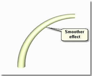
 - In the Modifier Stack select Cylinder. Note that the actual object is called Cylinder01. The entry in the modifier stack relates to the modifyable parameters for a cylinder object
- Change the Height segments to 20. This produces a smoother effect
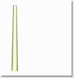
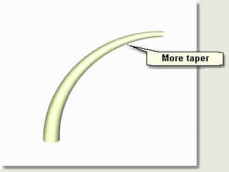
- Select Taper Change the Taper Amount to -0.7. This increases the taper
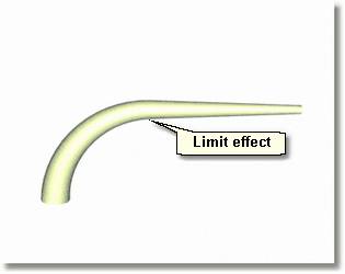
- Select Bend. Under Limits check Limit Effect. Change the Upper Limit to 10
- Select Cylinder and change the Radius to 0.3
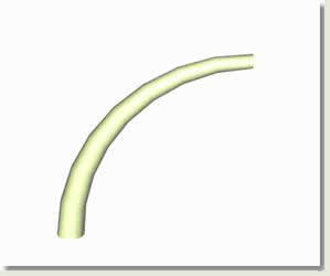
- Go to the top of The Stack and select Bend
- Click on the + sign to the left of 'Bend' to access the modifier's sub-objects and select Centre
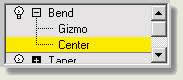
- In the Left Viewport use the Transform Gizmo to move the centre up and down. This moves the centre of bend up thus:
- Main Menu > Edit > Clone. Copy Cylinder01
- Select Cylinder02 and remove the modifiers by selecting them in the stack and pressing Remove modifier from the stack


- With Cylinder02 still selected change the Height to -20. Render the result. This lamp post is not completed, however, you have just used modifiers and The Stack to produce the elements for the main body of a lamp post
Modifiers for Infrastructure and Landscape
The list below identifies modifiers useful for infrastructure and landscape modelling. The modifiers underlined are explained fully in this section. The other modifiers are covered adequately in the MAX/VIX Help System. Bend and Taper modifiers were covered in the previous section
NOTE: The UVW Map and Map Scaler modifiers are covered in 'Materials, Lighting and Production'
Surface modelling
Cross Section / Surface
Normal
Noise
Displace
Normalize Spl.
Object modelling
Edit Spline
Edit Mesh
Extrude
Face Extrude
Bend
Taper
Twist
Skew
Stretch
Sweep
Lathe
Bevel
Bevel Profile
Fillet/Chamfer
Slice
Cap Holes
MeshSmooth
Lattice
Optimisation
Normalize Spl.
Subdivide
MultiRes
Substitute
Materials
UVW Map
MapScaler
- Use the MAX / VIZ User Reference to explore the use of all these modifiers and relate these to landscape tasks. Common modifiers are explored below:
Cross Section / Surface
To create a surface between two edges at different levels (or indeed at the same level) you can use two modifiers. Firstly the Cross Section modifier is used to create a framework, then the Surface modifier is used to create a surface from the framework. Splines can be added (before applying the modifiers) to smooth out slopes around corners for example. The splines may need to be reversed in the process to stop 'entanglement' and the surface modifier includes an option to flip the face normals if needs be
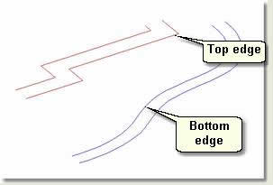
- Open kf204_06.max. This contains four lines representing a higher straight path and a lower curved path. You need to create a surface embankment between the two existing path edges and smooth the path near the angular top path as it would be in real-world construction. The edges can be created from path meshes using the Create Shape from Edges command (Ref 4.1 Mesh Editing) or by copying an existing edge and deleting unwanted segments
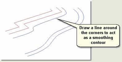
- Draw a smooth line in the top viewport around the sharp corners of the top path edge and move just below the edge. This will be used to adjust the smoothness around the corners later
- Select the top edge and rename Embankment
- Modify Panel / Geometry rollout / Attach. Attach the new line and then the bottom edge spline to make one spline object
NOTE: It is important to attach the splines in this order for the process to work ie do not select a line over another then back to the previous one
- Select Embankment
- Modify Panel / Cross Section modifier. This creates a framework for the new embankment surface
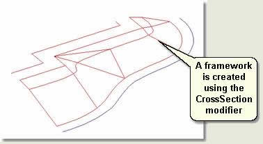
TIP: If the cross section framework appears to cross and become 'entangled' in the top viewport use spline sub-object editing to Show Vertex Numbers and Reverse to make sure the splines are all in the same direction. This will solve any entanglement
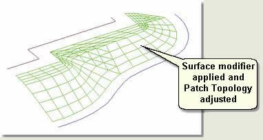
- Modify Panel / Surface modifier. This creates a surface using the cross section framework with a number of parameters. Change these thus:
- Spline Options / Flip Normals. If the normals are facing the wrong way check this box
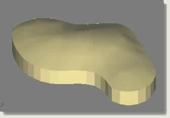
- Patch Topology. Change the number to 3. The surface should look like that shown in the image below
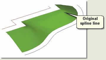
- Change the colour of the embankment to green
Editing the surface splines
- You can now go down the modifier stack and edit the height of the spline sub-object and vertices of the smoothing line in order to fine tune the surface. The line is being used as a design contour
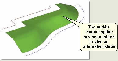
NOTE: As always, when finished creating and editing the surface convert it to an editable mesh to save on system resources
Extrude
The Extrude modifier extrudes lines or closed shapes along any axis depending on which viewport the line or shape has been drawn
- Draw a circle of 10 radius in the Top viewport and another in the Left viewport. Select both circles
- Modify Panel / Extrude modifier. Change the Amount spinner to extrude the circles
NOTE: When you change the amount on one the other extrudes as well. This is because when you select multiple objects and apply a modifier the modifier is instanced. To change the extrude on all objects de-select all then select one of the objects. Change the modifier parameters on the selected object and all the other objects respond
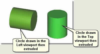
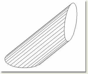
- Capping group box / Uncheck Cap Start and Cap End Notice that the end caps disappear. If geometry appears to be missing use Force 2-sided
- Delete the extruded circle drawn in the Left viewport to leave the vertically extruded circle
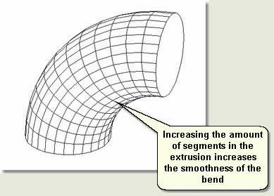
Increasing smoothness when used with other modifiers
- Wireframe display mode
- Modify Panel / Bend modifier / Parameters rollout. Apply a bend amount of 90. The circle is not bent smoothly, but at a straight angle thus:
- Go down the modifier stack to Extrude and change the Segments to 12. The circle is now extruded and bent in a smooth fashion using the number of segments in the extrusion to increase or decrease the smoothness
Using Sub-Object editing to create a bevel on a cylinder
This creates the base for a lamp post
- Open kf204_07.max. This scene contains an extruded circle. You will increase the segments and use Sub-Object vertex editing to create a bevel detail to the top of the extruded cylinder
- Select Lamp base. In the Modify Panel note that the extrusion has only one segment
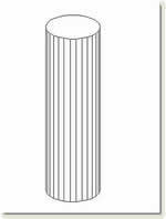
- Change the segment number to 2
- Convert the Lamp base to an editable mesh and in vertex sub object mode (Left viewport) move the middle segment vertices up to near the top of the cylinder
- In the Left viewport select the top vertices and use Transform Scale to decrease the size of the top vertices

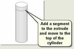
Lathe
The Lathe modifier creates a 3D object by rotating a shape or NURBS curve about an axis. In this exercise you will use the shape of a bollard taken from an external works product brochure and drawm accurately in AutoCAD
TIP: When creating shapes for lathes use AutoCAD, perhaps scanning an image from a brochure and accurately creating the shape at the correct size. Import this into MAX/VIZ, adjust the pivot point, rotate it in the viewport and move to 0 on the Z axis
- Open kf204_08.max. This scene contains the outline shape of a bollard. The important points to note are:
- Only half of the bollard shape is drawn as the shape is to be used to lathe around its axis
- The pivot point is at the centre bottom of the shape. This is the point around which the lathe is created
- The shape is vertical in the Left and Front viewports
- Select Bollard
- Modify anel / Lathe modifier. The shape is lathed around its pivot point
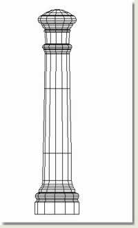
- Parameters rollout / Change the number of Segments to 16. This produces a smooth lathe:
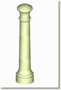
- To reduce the number of faces generated and perhaps add to the design, reduce the number of segments:
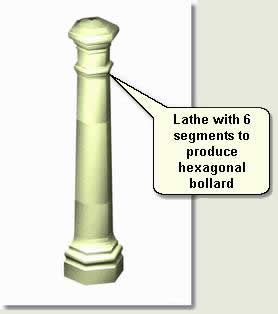
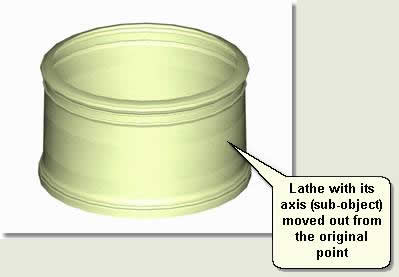
If required, and perhaps to create different effects, the axis point can be changed easily thus:
- In the Modifier Stack select the Axis sub-object of the lathe. In the viewport use the transform gizmo to move the axis out or in from the centre
NOTE: To edit the shape simply go down the modifier stack to the editable spline level and manipulate vertices, edges etc. The lathe will update automatically
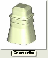
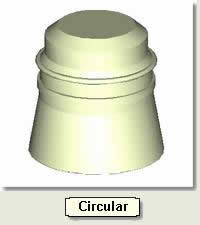
Bevel Profile
The Bevel Profile modifier extrudes a shape using another shape as the path. Unlike lofting it fails if you delete the original shape and is a modifier as oppose to a compound object. One of the main advantages of this modifier over the Lathe modifier and Loft compound object is that the geometry remains well ordered even when the path only has 4 or even 3 sides. Throughout this tutorial notice how the geometry is more uniform than a loft for example
In this example you create a base for a monument
- Open kf204_09.max. This scene contains an Ngon shape and a profile shape for the base that has been accurately drawn in AutoCAD
- Select Ngon01
- Modify Panel / Bevel Profile modifier
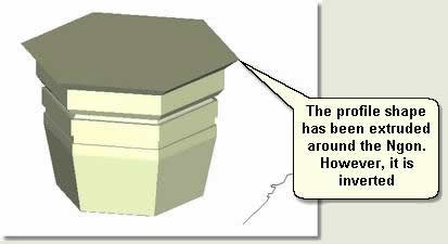
- Parameters rollout / Pick Profile. Select the profile shape Base profile in the viewport.
The profile is extruded arond the Ngon shape. However, The shape has been extruded 'inside out'. To change this you must change the rotation of the profile shape and then use an XForm modifier to make sure the changes are passed to the Bevel Profile modifier
NOTE: Many modifiers and other functions do not respect the transform controls on objects. Strange results sometimes appear if an object has been rotated or scaled (moving is not so affected) before applying the changes. If this happens check that the scale or rotation of the object is not 0,0,0. If not, try applying an XForm modifier before using the editing further and perhaps turning the object into an editable spline before carrying on (again, to save system resources)
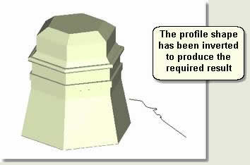
- Select Base profile shape
- Modify Panel / XForm modifier
- Use Rotate Transform Type-In to change the Y rotation to 180, thus inverting it. This flips the Bevel profile as required
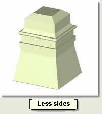
- Right click over the selected profile shape and Convert to Editable Spline. This ensures you do not use modifiers when you know you do not need to edit the object further
- Visit the Modifier Stack again and change the Ngon parameters for Sides, Corner Radius and Circular
MeshSmooth
The MeshSmooth modifier smooths meshes (believe it or not) and is useful wherever hard lines in meshes need to be controlled. In many ways this provides an alternative to the NURBS system of modelling (not covered in Key Fundamentals) where curves and smooth lines are an important feature of the object. This exercise uses the MeshSmooth modifier to smooth the edges of a box object used for the creation of a table top
- Open kf204_10.max. This scene contains a box object used for the creation of a table top
- Select Table top
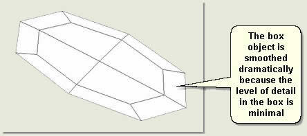
- Modify Panel / MeshSmooth modifier. This doesn't change anything until the iterations are increased from 0 (default)
- Subdivision Amount rollout / Change the Iterations to 1
The box is smoothed drastically. You need to alter the box properties to increase the detail at the corners
- Select Box in the Modify Stack and change the Length Segs to 15, the Width Segs to 15 and Height Segs to 8
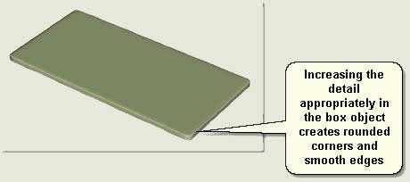
- To make the table top even smoother change the Iterations to 2 in the MeshSmooth parameters
NOTE: This demonstrates how parameters in a standard primitive object can be used in conjunction with the MeshSmooth modifier to achieve a required result. Of course other methods of creating a rounded edge table exist - using the Bevel Profile modifier, for example. The method shown above does produce a lot of faces
Subdivide
The Subdivide modifier breaks flat surfaces into meshes in a uniform fashion. Although developed for use in radiosity calculations (light bouncing off objects and onto other objects), this is a very useful tool that can be used in the creation of surface detail. In this example you take a planting bed that has been drawn as a closed polygon in AutoCAD convert it to an editable mesh and use the subdivide modifier to add uniform detail to the mesh. Then you will be able to use vertex sub-object editing to add relief to the bed
- Open kf204_11.max. This scene contains a Celtic Maze patio created in AutoCAD from closed polygons
- Select BEDS_INNER.18 and Isolate Selection
- Convert to Editable Mesh
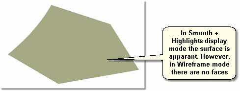
In Wireframe display mode the mesh does not appear to have any faces, although in Smooth + Highlights display mode the surface is there. To edit this surface and add relief for the planting bed you need to add uniform faces to the surface
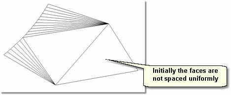
- Modify Panel / Subdivide modifier. Keep in Wireframe display to view the surface faces. Initially the faces are not spaced uniformly
- Change the Spinner Snap to 2 decimal places and 0.01Snap and Turn On
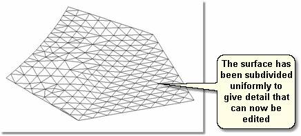
- Move the spinner down to about 1, then slowly down to 0.15. Notice in the viewport that uniform detail is being added to the surface
TIP: If you take tha spinner down to 0 the program 'hangs' and stops working. To remedy this situation pres Esc a few times. Notice that in the Update rollout the setting changes to Manual. Move the spinner up to say 2 and change the setting to Automatic. You will then be able to continue using the modifier
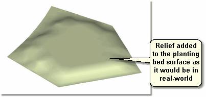
Adding relief to the planting bed
- Select the bed surface and Convert to Editable Mesh
- Enter Vertex sub-object mode and turn on Soft Selection
- In the Top viewport use the Fence Selection Region to select vertices near to the edge (but not on any edge) and alter the Soft Selection parameters to produce a smooth transform
- In the User viewport use the tansform gizmo to raise the selected vertices slightly to give relief to the planting bed thus:
- Exit Isolation to see the new bed surface in context
MultiRes
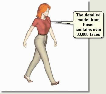
The MultiRes modifier decreases the number of vertices and polygons in an object. It offers several advantages over the Optimize modifier, including faster operation and the ability to specify reduction as an exact percentage or vertex count. In this example you use the MultiRes modifier to reduce the number of faces in a model of a person imported from Poser software
- Open kf204_12.max. This scene contains a model of a woman imported in 3DS format from Poser
- Wireframe display mode. Right click over the selected woman and under Properties notice that the model contains over 33,000 faces
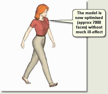
Unless close work is needed, the face number needs bringing down to about 7000 faces to save on system resources whilst still having the desired effect
- Modify Panel / MultiRes modifier. Press Generate and wait until Mesh Generated appears below this button
- Whilst looking at the Faces: count to see the ratio of new faces to old, reduce the Percent spinner to reduce the number of faces to about 7000
Using these parameters reduce the faces in the model further to about 3000 faces
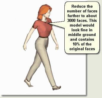
- When happy with the result Convert to Editable Mesh
Donate to CADTutor
If you found this tutorial useful, you might like to consider making a donation. All content on this site is provided free of charge and we hope to keep it that way. However, running a site like CADTutor does cost money and you can help to improve the service and to guarantee its future by donating a small amount. We guess that you probably wouldn't miss $5.00 but it would make all the difference to us.
Local Navigation
Sponsored Links
The Basics
- Dual Dimensions in a Dim…
- UCSICON Options
- "Best of" Basics: Irreg…
- Tool Palette Basics
- Original Dimension Value
- Possible Solutions to th…
- Avoid Using 'Standard' i…
- Shorten the Plot Scales…
- Update the Source File B…
- User Increment Angles fo…
- Drawing Information
- 'Sign Language'
- Rotate with the Copy Opt…
- Use the INSERT Osnap on…
- To or From the Current L…


