Learn AutoCAD with our Free Tutorials
Welcome to CADTutor
CADTutor provides the best free tutorials and articles for AutoCAD, 3ds Max and associated applications along with a friendly community forum. If you need to learn AutoCAD, or you want to be more productive, you're in the right place. See our tip of the day to start learning right now!
Free Tutorials and More…
The Tutorials section provides over 100 original tutorials for AutoCAD, 3ds Max and other design applications. Michael’s Corner is an archive of productivity articles that brings you the best AutoCAD tips and tricks. Our Forum is a lively community where AutoCAD users can ask questions and get answers. The Downloads area provides free AutoCAD blocks, free AutoLISP routines and free images.
Tutorials of the Moment
Recently viewed tutorials
-
Direct Distance Entry

The essential way of working with AutoCAD Format: Text/Image
Last visited: less than one minute ago
-
The Interface

This tutorial gives a brief explanation of the MAX interface items commonly used and introduces you to the important areas of the interface. Format: Text/Image
Last visited: 1 minute ago
-
Dimensioning

This tutorial describes the options and commands available for dimensioning drawings and how to use them. The correct use of AutoCADs dimension tools is the key to producing clear and concise measured drawings. Format: Text/Image
Last visited: 2 minutes ago
-
AutoLISP Quick Start

This tutorial is designed to help AutoCAD users get to grips with AutoLISP quickly. It demonstartes how to create AutoLISP routines from a standing start. Format: Text/Image
Last visited: 2 minutes ago
-
Object Snap

A tutorial giving an overview of all the AutoCAD object snaps (osnaps) with some worked examples. The tutorial also covers the use of temporary tracking points and object snap tracking. Format: Text/Image
Last visited: 4 minutes ago
-
AutoCAD to Photoshop

This tutorial demonstrates a number of workflows from quick and simple to high quality. Format: Text/Image
Last visited: 6 minutes ago
CADTutor Tutorials
Our tutorials are comprehensive but straightforward introductions to AutoCAD and related software. They are designed to help beginners get to grips with design workflows as quickly as possible. There are over 100 to choose from, some text/image based and others in video format. Whatever stage you are at in your learning, you should find a tutorial to help.
Forum Latest
Currently Active Topics
custom .pc3 not supported
by harimaddddy
0 replies
Last post: 44 minutes ago
line space factors
by masterfal
0 replies
Last post: 2 hours ago
Batch run a lisp program
by C. Roberts
6 replies
Last post: 5 hours ago
Spacing text efficiently
by benjs1
3 replies
Last post: 5 hours ago
APİ call in AutoLisp
by p7q
20 replies
Last post: 5 hours ago
Locking a viewport in paperspace
by DODGE
13 replies
Last post: 17 hours ago
This Week's Hot Topics
Detecting privileges with Lisp
by PGia
6 replies
Viewed: 248 times
Batch run a lisp program
by C. Roberts
6 replies
Viewed: 183 times
Help me to fix an old viwport grid lisp.
by mhy3sx
5 replies
Viewed: 150 times
Automatic sorting of lines by LandXML Attributes
by mg1409
4 replies
Viewed: 260 times
Spacing text efficiently
by benjs1
3 replies
Viewed: 88 times
Upper Slab Drawing How to Draw Autocad
by 신민수
2 replies
Viewed: 151 times
CADTutor Forums
Our forum is a vibrant community of experts and beginners. The main focus is helping beginners get to grips with AutoCAD and to help more advanced users become more productive. The AutoLISP forum is one of the busiest out there, providing expert advice for busy professionals.
AutoCAD Productivity
Drawing Information
From: AutoCAD Productivity Articles #137
Originally published: December 2014
For billing purposes, it's nice to know how long you have spent working in a drawing. To that end, the Time command may be a helpful resource, especially given the elapsed time feature that can be toggled ON and OFF, and can also be Reset.
Command:  TIME
Current time:             Sunday, November 23, 2014  3:44:54:790 PM
Times for this drawing:
  Created:                Wednesday, November 14, 2007  2:42:44:984 PM
  Last updated:           Sunday, November 23, 2014  9:59:28:105 AM
  Total editing time:     0 days 04:45:06:399
  Elapsed timer (off):    0 days 04:44:32:866
  Next automatic save in: 0 days 00:07:30:395

Enter option [Display/ON/OFF/Reset]:
 To keep track of your time in the drawing, launch the Time command, then begin the elapsed timer with the ON option. When finished, use the OFF option to display the total editing time. The above information indicates that I was editing the drawing for a little more than 30 seconds - 04:44:32 to 04:45:06.
DWGPROPS [] Another useful tool for quick information may be the Dwgprops command found in the ‘scarlet letter’. It's nice to have the Location and Size information immediately available, rather than going out to Save As.
See all the articles published in December 2014
Michael's Corner
Between 2003 and 2016, Michael Beall (and one or two guests) wrote almost 600 articles for CADTutor. The focus of these articles is AutoCAD productivity, and although some of them are now more than a few years old, most remain relevant to current versions of AutoCAD. The article above is just one example. Check out Michael's Corner for a full listing.
Image of the Week
-
30th June to 6th July 2025

This week's image is by Lazarus
Software used: AutoCAD 2009
-
Last Week's Image

Last week's image is by neekcotrack
Software used: AutoCAD 2005
-
Two Weeks Ago

This image is by papagyi
Software used: AutoCAD 2009
-
Three Weeks Ago

This image is by nocturne00
Software used: AutoCAD 2006
Gallery of Work
Over the years, our forum members have contributed hundreds of images, showcasing their amazing work. The images above are just a small selection that demonstrate the wide range of project types our community is involved with. Take a look at our gallery to see all the images published in the last 12 months.
Tip of the Day
Command line in a window (F2)
The command line can be very useful, especially for beginners because AutoCAD often gives useful prompts which helps when learning how to use some of the more complicated commands. The command line is also used by AutoCAD to report information back to the user, but sometimes that information may run to several lines of text, and disappear from view. A good example of this is the Distance command (you can run this from the keyboard by typing DIST). The problem is that by default, the command line is only two lines high and so if you use the Distance command, you don't even see the distance reported to the command line.
One way round this problem is to increase the depth of the command line to show more lines but this takes up valuable drawing area. A better solution is to display the command window using the F2 key on the keyboard.
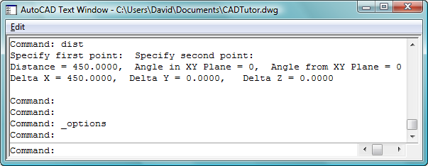
As you can see above, the command window also allows you to scroll back through the command line so that you can review your recent drawing history.
Missed a Tip?
Did you miss yesterday's tip? Maybe you forgot to drop by or maybe you don't visit over the weekend. If so, you can now see all the tips published during the past week. Also, if you have a tip you'd like to share with us, you can post it on our forum and if we like it, we'll publish it here.