

Stage 3: Create Surfaces
Introduction
Production of seamless surfaces for roads, pavements, grassed areas and planting beds is probably the most important stage in the creation of a 3D landscape scene. Level of detail (number and spacing of vertices on surface boundary lines and landform mesh) is critical, hence the attention to detail starting in AutoCAD through manipulation of splines and vertices in MAX/VIZ. Get this process ingrained and surface creation will become a straightforward task
This stage involves creation of distinct surfaces that can be improved further by adding relief (to soft landscape areas) and materials
3.1 Cut and Surface using Key 3D Surfaces routine
- Carry on from the previous scene or open ACAD to 3D Stage 2c.max
- In the User viewport unhide Landform
- Change the display mode to Facets + Highlights. This displays the edges of surfaces within the landform better
- Select the Landform and open Key 3D Surfaces

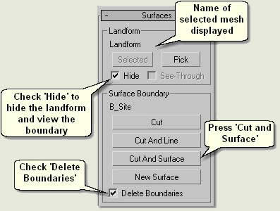
- Press Selected to display the name Landform under 'Landform' on the interface. This is the landform mesh from which to cut and create a new surfaces
- Check Hide if the boundary lines are difficult to view under the landform
- In the viewport select the site boundary: B_Site. The name will then automatically appear under 'Surface Boundary'
- Check Delete Boundaries. This deletes the boundary after the surface is created
- Finally, press Cut and Surface. This cuts the landform and creates a new surface within the mesh called B_Site.01 Surface
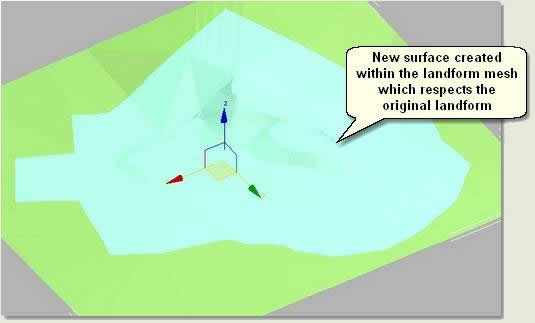
- Hide the landform mesh. This can be displayed later and can be used to add aerial imagery to put the site into context
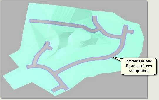
- Repeat this process, selecting the Surface_B_Site as the landform. Select all four pavement boundaries and press Cut and Surface. This automatically cuts and surfaces the pavement surfaces in turn
- When completed, check that the surfaces are good and Attach the pavement surfaces together
- Change the colour if required
- Next, Cut and Surface the Road in the same way
NOTE: If faces are missing or extra faces exist where they should not be, then use sub-object editing such as welding vertices and deleting faces to correct these issues at this stage. Good attention to the previous stages of production should, however minimise any extra work here
Finally, create independant path surfaces thus:
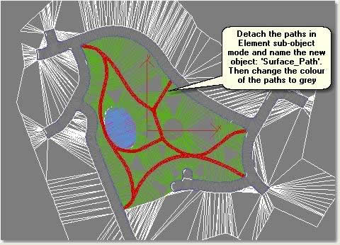
- Select Surface_B_Site
- In Element sub-object mode select the inner paths and detach these faces. Name the detached surface mesh: Surface_Paths
- Exit sub-object mode and change the colour of the paths to grey
Remove isolated vertices
After creating surfaces check that no isolated vertices exist on each surface. These are vertices that exist away from the main surface mesh and are a result of the cutting and surfacing process
- Simply enter vertex sub object mode for each surface and on the Edit Geometry rollout press Remove Isolated Vertices. Remaining isolated vertices that are not removed (because they form an isolated edge) can be deleted manually
NOTE: If the Key 3D Update routine is used when isolated vertices exist, bounding boxes may still be away from the surfaces. This is an indication that isolated vertices exist
3.2 Add relief to grassed areas
Alter level of detail on surface meshes
Before adding relief to an area enough faces need to exist on the mesh. Control of the number of faces and uniformity of faces on a mesh can be acheived using the Subdivide modifier and Key 3D Simplify Mesh
- Carry on from the previous scene or open ACAD to 3D Stage 3b.max
- Select one of the grass surfaces and notice it comprises long thin faces. This because the Terrain object simply 'joins the dots' on the boundary spline
NOTE: The addition of contour data (within the 3D spline areas) when producing the 3D spline model puts extra design detail where required and helps to reduce this 'embankment' effect
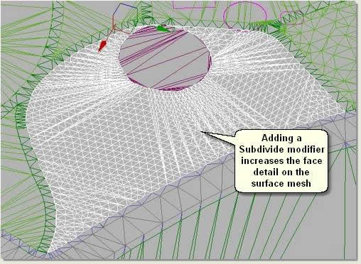
- Apply a Subdivide modifier and reduce the Size amount carefully using the spinner until the face detail is increased dramatically
TIP: If the Size is reduced to 0 the computer will 'hang'. To correct this press Esc. To carry on, change the Update setting back to Automatic
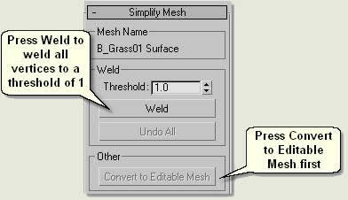
- Open Key 3D Surfaces dropdown menu > Key 3D Simplify Mesh
- Keep the surface mesh selected and press Convert to Editable Mesh
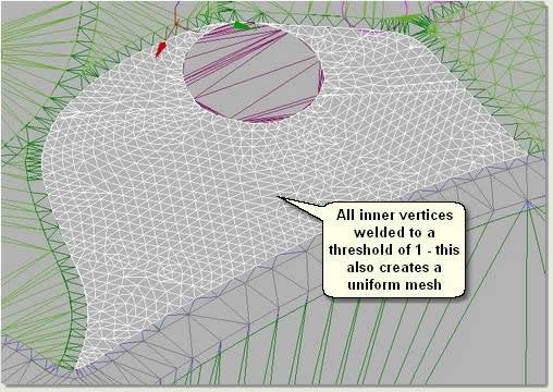
- Type 1 in the Weld Threshold spinner and Weld. All the vertices apart from vertices at the edge of the mesh are welded to a threshold of 1 (ie any vertices less than 1m apart are welded
Add Relief
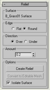
- Select the surface mesh and open Key 3D Relief

- Under Edge select Round
- Under Direction keep on default Over
- Type 0.2 in the Amount spinner
- Press Create Relief. This moves the mesh up 0.2m, but leaves the edges where they were
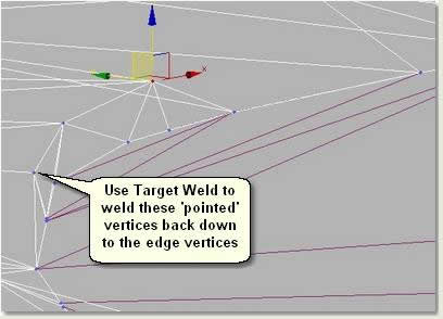
- Notice that on some sections the mesh vertices which are near to the edge have been moved up vertically creating an almost vertical pointed edge. Use Target Weld to move and auto-weld the offending 'points' back down to the edge vertices
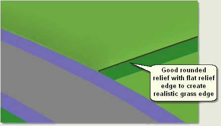
- Use Key 3D Relief again, but this time choose Flat and Over with Amount 0.1. This raises the mesh up again, but gives flat relief to represent a cut grass edge
- Weld and Target Weld any stray vertices
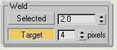
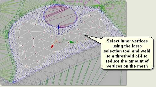
- Finally select vertices in the middle of the grass mesh ie away from the edge and weld vertices to a threhold of 4
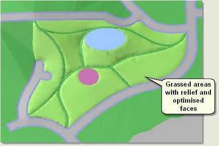
- Repeat this process on the remaining grass areas to produce optimised meshes with rounded relief and flat relief edges simulating grassed areas
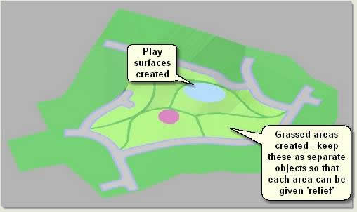
3.3 Create Play surfaces
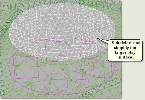
- Subdive and simplify the larger play surface
- Cut and Surface the play area using the remaining play surface boundaries. Using Key 3D Surfaces select all the boundaries at once before using Cut and Surface
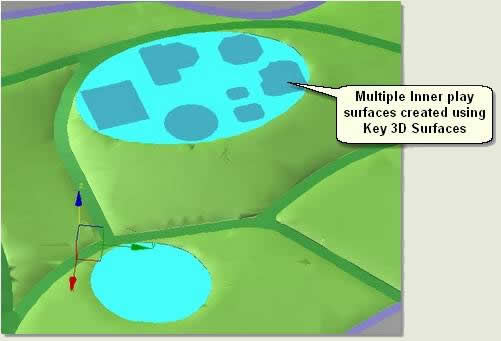
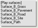
- Finally, change the display colours of the play surfaces and group all play surfaces together
- Select Surface_ B_Grass01 and Attach all the remaining grass surfaces to create one object. The scene should now contain the following objects (plus the context surface which is hidden):
Donate to CADTutor
If you found this tutorial useful, you might like to consider making a donation. All content on this site is provided free of charge and we hope to keep it that way. However, running a site like CADTutor does cost money and you can help to improve the service and to guarantee its future by donating a small amount. We guess that you probably wouldn't miss $5.00 but it would make all the difference to us.
Local Navigation
Sponsored Links

The Basics
- Dual Dimensions in a Dim…
- UCSICON Options
- "Best of" Basics: Irreg…
- Tool Palette Basics
- Original Dimension Value
- Possible Solutions to th…
- Avoid Using 'Standard' i…
- Shorten the Plot Scales…
- Update the Source File B…
- User Increment Angles fo…
- Drawing Information
- 'Sign Language'
- Rotate with the Copy Opt…
- Use the INSERT Osnap on…
- To or From the Current L…


