Transforming Objects
Introduction
Transforming objects means changing the position, size or number of an object without altering the integrity of the geometry itself. MAX / VIZ offers a host of transformation tools to do these tasks. The main transformation tools used for landscape work are as follows:
Move
Rotate
Scale
Pivot Point transform
Clone
Align
Snap
Download Sample Data
kf203_files.zip (215kb)
module_2_maps.zip (5.9mb)
Move
Move objects by using the Transform Gizmo in the viewport or the Transform Type-In floater
- Open kf203_01.max. This scene contains a litter bin
- Select Litter bin
- Main Toolbar > Select and Move
 When this button is orange you are in Select and Move mode. In the viewport the Transform Gizmo is displayed. This 'helper' gives you the ability to move the object along just one axis at a time
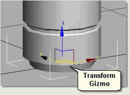
- In the User viewport move the cursor over each of the x, y and z axis in turn and notice each axis turns yellow . When this happens over one axis left click and drag the cursor to move the object along that axis only
- In the Top viewport left click and drag the centre square handle to move and position the litter bin without restriction
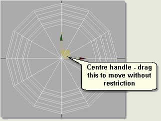
- In order to move the litter bin more accurately use the Transform Type-In floater:
- Main Toolbar > Select and Move Right click on this button when it is active (orange) to display the Transform Type-In floater This allows you to type in values or use the spinners to move the object. Use Absolute values to move to World coordinates or Offset values to move in relation to the bin's current position
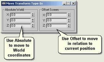
TIP: Use Spinner Snap (Ref: KV01) to increase or decrease the accuracy of the spinner values on each click. Also, whilst using a spinner the value can be set back to 0 by right clicking
Rotate
Rotate objects by using the Transform Gizmo in the viewport or the Transform Type-In floater
- Open kf203_01.max if not already open. This scene contains a litter bin
- Select Litter bin
- Main Toolbar > Select and Rotate
 When this button is orange you are in Select and Rotate mode. In the viewport the Transform Gizmo is displayed. This 'helper' gives you the ability to rotate the object along just one axis at a time
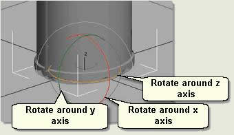
- For landscape work the viewports are usually used to position objects and it is only these three helpers on the gizmo you need to use. Notice that the outside circle rotates the object in relation to the view and that if you place the cursor in the middle of the gizmo the centre sphere turns grey. This rotates arbitrarily - this functionality is rarely needed
- In order to move the litter bin more accurately use the Transform Type-In floater:
- Main Toolbar > Select and Rotate Right click on this button when it is active (orange) to display the Transform Type-In floater This allows you to type in values or use the spinners to rotate the object. Use Absolute values to move to World coordinates or Offset values to move in relation to the bin's current rotation
Scale
Scale objects by using the Transform Gizmo in the viewport or the Transform Type-In floater
- Open kf203_01.max if not already open. This scene contains a litter bin
- Select Litter bin
- Main Toolbar > Select and Scale
 When this button is orange you are in Select and Scale mode. In the viewport the Transform Gizmo is displayed. This 'helper' gives you the ability to scale the object along just one axis at a time. Place your cursor over the positions illustrated below and left click and drag to scale along individual axis or uniformly along x,y,z
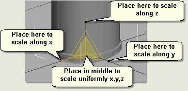
NOTE: Other scaling options exist if you place the cursor over the edges of the gizmo triangle. This is not a desirable way of scaling as it is arbitrary
NOTE: Most scaling is done along all three axis at the same time (ie using the middle handle). A good example of when you would just scale along x,z or just z is when you need to randomise / scale trees and shrubs
- In order to scale the litter bin more accurately use the Transform Type-In floater:
- Main Toolbar > Select and Scale Right click on this button when it is active (orange) to display the Transform Type-In floater This allows you to type in values or use the spinners to scale the object
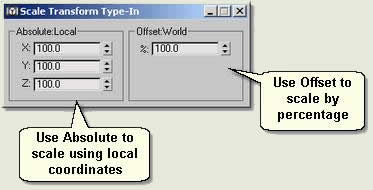
Use Absolute values to scale using local coordinates or Offset values to scale by percentage
Pivot Point Transform
Each object has a Pivot Point. This is the point around which an object is transformed. The position of an objects pivot point becomes important when, for example, you require to rotate an object in the viewport accurately around its pivot point. A gate rotating around a hinge, or the ability to rotate a ramp up or down from one end are examples of where the position of the pivot point of an object needs attention
NOTE: Pivot Points are extremely important when animating mechanical assemblies or in character animation. Here, one object such as the arm of a piston rotates around its pivot point and is linked to other parts of an assembly by another object's pivot. This is why the pivot moving tools are found on the Hierarchy Panel
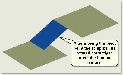
- Open kf203_02.max. This scene contains a top surface, a bottom surface and a ramp that needs rotating from the top down to meet the bottom surface
- Select Ramp Notice that the pivot point is at the centre of the ramp. Rotate the ramp along the y axis using the transform gizmo and notice that it is impossible to rotate it from the top surface. To enable this to be done you will have to move the ramp's pivot point to where the ramp meets the top surface
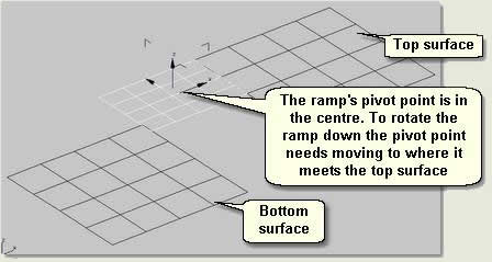
- Maximise the Top viewport
- Hierarchy Panel > [Pivot] > [Affect Pivot Only] This button turns blue showing it is active. The Pivot point changes to show that you are in pivot tranforming mode
- Press Select and Move
- Position the cursor over the x axis and drag the pivot point to where the ramp meets the top surface
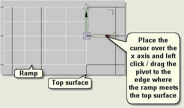
NOTE: Normally you would use snaps to accurately 'snap' the pivot point onto the ramp edge. Snaps are covered later in this tutorial. For now, position the pivot as accurately as possible without snaps
- Press Affect Pivot Only again to exit the pivot transform mode. The button turns grey and the pivot returns to normal in the viewport
- Maximise the User viewport and rotate the ramp accurately (using Transform Type-In and Spinner Snap) around the new pivot point position
Clone
The ability to copy objects in MAX / VIZ is called 'cloning'. This is different to just 'copy' because you have three options for how the new object's are created and how they behave after creation. This tutorial explains the main two options of 'Copy' and 'Instance', with a brief explanation of the third method, 'Reference'
- Open kf203_03.max. This scene contains a simple cylinder
- Select Cylinder01
- Main Menu > Edit > Clone The Clone Options dialog is displayed. The new clone is automatically renamed 'Cylinder02'. Either type in a new name or leave the default name in the text box
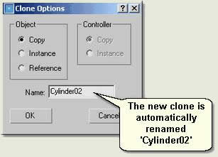
- Select Copy then press OK. In the viewport the cylinder appears not to have been copied. Notice that the selected object is the new clone, so the clone must have been placed exactly over the original cylinder
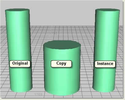
- Select and Move Using the Transform Gizmo move the copy clone along the x axis so that it sits next to the original cylinder
- Select Cylinder01 again
- Repeat the cloning procedure, however, this time select Instance on the Clone Options dialog
- Select and Move Using the Transform Gizmo move the instance clone along the x axis so that it sits next to the original and copied cylinders
- Select Cylinder01
- Modify Panel > Parameters rollout Change the parameters for radius and height etc and notice that the instanced cylinder takes on the changes, whereas the copied cylinder does not. This is the difference between an instance and a copy
NOTE: References are used when you want to 'refer' to a wall 'shape' for example whilst building a 3D wall. The reference is transformed (made to stand up) and extruded (modified) to create a 3D wall. You can add windows to the original wall shape and these changes will be referenced in the 3D wall
TIP: Use instances whenever you can to cut down on repetative procedures and when you know you may need to globally change the parameters of a number of objects that are the same (columns for example) in the future
Quick Cloning
As ever, there is a quick way of cloning. Simply select the object/s to be cloned and keep the Shift Key down whilst carrying out Select and Move / Rotate / Scale. The Clone Options dialog is displayed after the transformation has been made
Aligning
Aligning means moving or cloning and moving one object in relation to the position of another object. The main tools used to align objects for landscape work are found on Main Menu > Tools :
Mirror
Align
Array
Spacing Tool
Mirror
Mirror is an invaluable tool for cutting down modelling tasks. If a shape or geometry is repeated on either side, for example in an entrance feature or paving pattern, use mirror to create an exact mirrored copy. In this way you only have to create half the shape or geometry
- Open kf203_04.max. This scene contains half an entrance feature shape ready for mirroring
- Select Gateway
- Main Menu > Tools > Mirror This displays the Mirror: Screen Coordinates dialog
- Change the settings as shown below
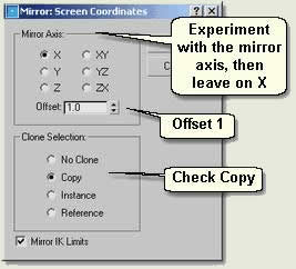
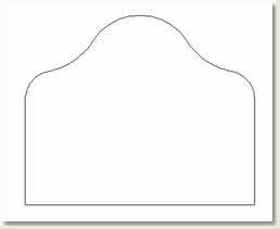
- The above shape is created using just half of the geometry. This can then be 'Attached' (Ref: KV03) and extruded (after making sure vertices are welded) to create a gate, or used for a boolean subtraction to create an entrance feature
Align
Aligning allows you to accurately place one object in relation to another object. You move the current selected object and align it to a target selected object
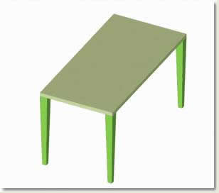
- Open kf203_05.max. This scene contains a table top and four table legs. You will align each leg to the corners of the table using the Align dialog
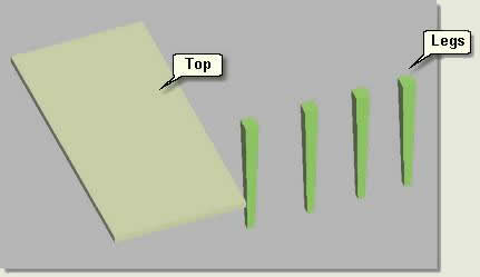
- Select Leg01
- Main Menu > Tools > Align the cursor changes to the align cursor (two boxes aligned) prompting you to select the target object. Select Top
- On the Align Selection dialog check X and Y
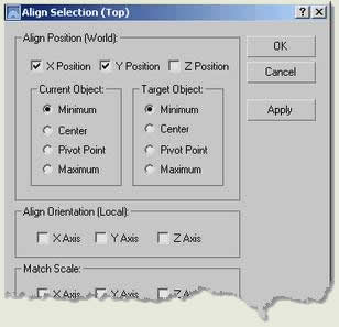
- Under Current Object check Minimum and under Target Object check Minimum Notice in the Top viewport the leg moves correctly to the bottom left corner of the table top. The minimum extents of the leg is aligned to the minimum extents of the table top on the X,Y plane
TIP: Keep the Top viewport showing and in wireframe display mode whilst aligning to show what is happening on the x and y plane
- Press Apply This applies the changes allowing you to now deal with the Z alignment and unchecks the Position checkboxes.
- Keep the dialog displayed and check Z
- Under Current Object check Maximum and under Target Object check Minimum Notice in the User viewport the leg moves correctly up to the corner of the table top. The maximum extents of the leg is aligned to the minimum extents of the table top on the Z plane
- Repeat this procedure to align Leg02 to the opposite corner
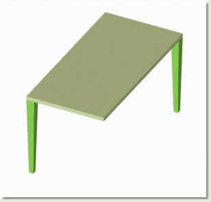
- Select Leg03 and open the Align dialog
- Check just Z
- Under Current Object check Maximum and under Target Object check Minimum
- Press Apply The leg is positioned correctly on the Z axis
- Check just X
- Under Current Object check Minimum and under Target Object check Minimum
- Check just Y
- Under Current Object check Maximum and under Target Object check Maximum The Leg moves to the correct top left position
- Repeat this procedure to align Leg04 to the opposite corner
Array
The Array tool is used to clone objects repeatedly along one, two or three axis all at the same time, giving instant results for the positioning of columns, trees in a plaza, lamp posts on a car park etc
Key Fundamentals describes the more straightforward linear array. For circular and spiral arrays consult MAX / VIZ Help
- Open kf203_06.max. This scene contains a cylinder and a box object with 10 width and length segments. The box helps to show the X and Y spacings for this exercise
- Select Column
- Main Menu > Tools > Array You are going to produce a one dimensional array for the column, then a two dimensional array
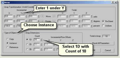
- On the Array dialog change the settings thus:
- Under Array Transformation enter 1 in the Y box. This moves each clone a distance of 1 unit
- Choose Instance under Type of Object This means you can alter the height of the columns globally
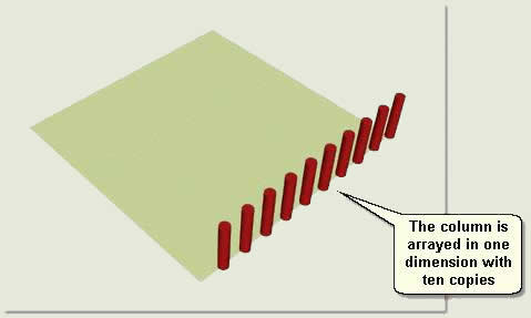
- Under Array Dimensions select 1D and Count 10 This creates 10 instances of the column
- Press OK
To Create a 2 Dimensional Array
- Undo the Array command
- Select Column again
- Main Menu > Tools > Array
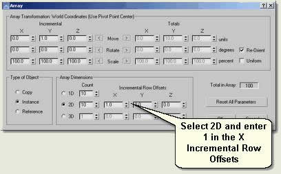
- On the Array dialog change the settings thus:
- Under Array Transformation enter 1 in the Y box
- Choose Instance under Type of Object
- Under Array Dimensions select 2D, Count 10 and enter 1.0 in the X Incremental Row Offsets This offsets the 1D row ten times by units of 1
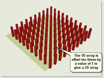
TIP: Experiment with the Array tools changing the Array Transformations and Array Dimensions until you are familiar with how it works. Use Undo to get back to the start each time you implement an array
Spacing Tool
The Spacing Tool is useful for spacing objects such as lamp posts, bollards, trees etc along a road or any other 'path'. You can alter the spacings accurately and make objects 'follow' the path so that lamp posts follow the line of a road for example
- Open kf203_07.max. This scene contains a road surface through a context landform and a Lamp Post. A camera is animated to follow the road. Move the Time Slider and view the Camera viewport to see the camera move along the road
- Select Lamp Post
- Main Menu > Tools > Spacing Tool
- Pick Path Use Select by Name to select Lamp Path
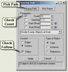
- Under Parameters check Count This allows you to change the number of copies and view the spacing below
- Select Divide Evenly, Objects at Ends
- Under Context check Follow The lamp post lamps will then follow the line of the road
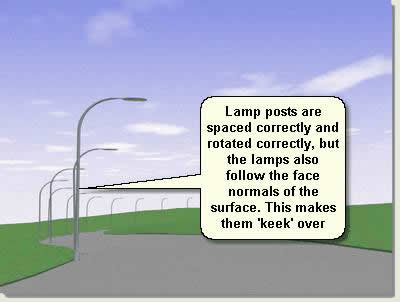
- Notice, however, that although the lamp posts lamps are rotated to follow the line of the road, they also align to the face normals on the Z axis
- Uncheck Follow. This keeps the spacing and makes the posts go vertical, but also keeps the Z rotation at 0
- Press Apply
- Manually rotate each lamp post to its correct rotation on the Z axis
- Move the camera along the road and render the scene to view the result
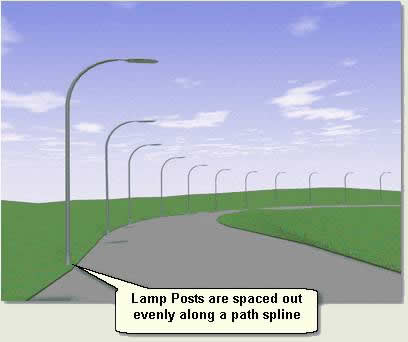
- Delete the copies and practice using the spacing tool again with other spacing settings
Snap
Use 3D snaps when possible for quick positioning of objects in relation to other objects. You can also control rotational movement by using 'angle snap' and scaling by 'percentage snap'. 2D and 2.5D snaps are not covered by Key Fundamentals because they have limited use in landscape work, however, explore these at your leisure
3D Snaps
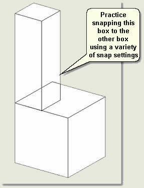
- Open kf203_08.max. This scene contains two boxes. You will snap one box to the other using a variety of snapping settings to demonstrate the main functionality of snaps
- Main Toolbar > 3D Snap Toggle
 The button turns orange when active
 - Right click over the button to access the Snap Settings dialog
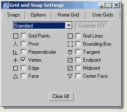
- Check Vertex then close the dialog
- Press Select and Move
- Select Move Box and hover the cursor over a vertex. The cursor changes to the move and snap cursor. Left click and drag the box over one of the vertices of Target Box The box snaps into place over the vertex
- Practice snapping the Move Box over the Target Box using Pivot, Vertex, Edge, Endpoint, Midpoint. Check Vertex and Midpoint, for example, to move a vertex of the Move Box to the midpoint of the Target Box
- Practice drawing a line with snaps using a variety of snap settings to snap the line to the boxes
Angle Snaps
- Select Move Box
- Main Toolbar > Select and Rotate
- Main Toolbar > Angle Snap Toggle
 The button turns orange when active
 - Right click over the button to access the Options Tab on the Snap Settings dialog
- Change the angle snap to 10 degrees then close the dialog
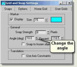
- In the viewport rotate the box using the Transform Gizmo Notice that the box rotates in 10 degree increments
Percentage Snaps
- Select Move Box
- Main Toolbar > Select and Scale
- Main Toolbar > Percentage Snap Toggle
 The button turns orange when active
 - Right click over the button to access the Options Tab on the Snap Settings dialog
- Change the Percent snap to 120 then close the dialog
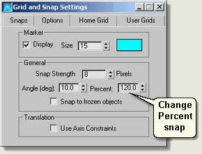
- In the viewport scale the box using the Transform Gizmo Notice that the box scales by 120 degree increments
Donate to CADTutor
If you found this tutorial useful, you might like to consider making a donation. All content on this site is provided free of charge and we hope to keep it that way. However, running a site like CADTutor does cost money and you can help to improve the service and to guarantee its future by donating a small amount. We guess that you probably wouldn't miss $5.00 but it would make all the difference to us.
Local Navigation
Wednesday
9th April 2025
Sponsored Links
The Basics
- Dual Dimensions in a Dim…
- UCSICON Options
- "Best of" Basics: Irreg…
- Tool Palette Basics
- Original Dimension Value
- Possible Solutions to th…
- Avoid Using 'Standard' i…
- Shorten the Plot Scales…
- Update the Source File B…
- User Increment Angles fo…
- Drawing Information
- 'Sign Language'
- Rotate with the Copy Opt…
- Use the INSERT Osnap on…
- To or From the Current L…


