

Multi/Sub-Object materials
Introduction
A Multi/Sub-Object material is a container for a number of sub-materials. This type of material is used when you need to assign different materials to different parts of an object and is used in infrastructure and environment projects mainly for objects such as benches, tables, lamposts, buildings etc. The Material IDs of the elements that make up the object are changed to correspond with the material number (or ID) contained within the Multi/Sub-Object that is assigned to that object. The element (seating legs for example) will the 'pick-up' the material with the corresponding number
This tutorial starts with a simple Multi/Sub-Object material containing standard none mapped sub materials. It then looks at a Multi/Sub-Object material including one mapped material and explains how to adjust the mapping. It concludes with a routine for adjusting the mapping independently on an object with six sub materials assigned
Download Sample Data
kf409_files.zip (422kb)
Open kf409_01.max. This follows on from the previous tutorial
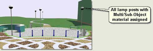
Lamp posts
- Select Lighting amenity 01 and Isolate Selection
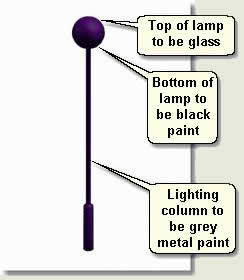
- Go to the Element sub object level and in the viewport select the top of the lamp. Shade Selected Faces has been checked on in the Viewport Configuration dialog so you can see the selected element. This element will be the glass part of the lamp
- Surface Properties rollout > Material. Notice that the Material ID has been set to to 3. This part of the lamp will pick up on sub-material number 3 (glass)
- Select the bottom half of the lamp and notice that the Material ID has been set to 2. This part of the lamp will now pick up on sub-material number 2 (black paint)
- Select the top and bottom of the lighting column and notice that the Material ID has been set to 1. This part of the lamp will now pick up on sub-material number 1 (grey metal)
- Exit out of sub-object mode and open the Material Editor
- Select a new sample window and press the Material Type button (thie defaults to Standard). Select Multi/Sub-Object and when prompted elect to Discard Old Material
- Name the new material Lamp post
![]()
The Multi/Sub-Object material has effectively another level on top of all the other materials contained within it allowing you to choose and edit each material separately when required
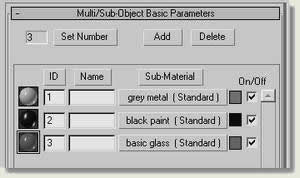
- Press Set Number and alter to 3
- Press the first Sub Material button with ID 1 to access the first sub material. Notice that this is just another standard material with all the parameters found when starting a material from scratch. Rename the sub-material grey metal
- Create a mid grey material with Specular level 90 and Glossiness 70. This give a good grey metal paint
- Press Go to Parent to go back to the Multi/Sub-Object Basic Parameters and press the next Sub Material button with ID 2
- Call this material black paint and create a black paint effect using the Anisotropic shader parameters
- Press Go to Parent again to go back to the Multi/Sub-Object Basic Parameters and press the third Sub Material button with ID 3
- Call this material basic glass and create a transparent glass effect using the Anisotropic shader parameters thus:
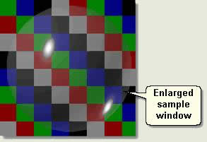
- On the Anisotropic shader parameters change the Diffuse colour to light grey, Specular Level to 120, Glossiness to 80 and Opacity to 40.This gives a basic glass effect that, although doesn't reflect and refract light is adequate for the purpose. Use the chequered background in the sample window to view the results and double click on the sample window to show a larger window if required
- Press Go to Parent again to go back to the Multi/Sub-Object Basic Parameters. The material top level should look like the image below
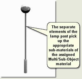
- With the lamp post still selected Assign Material to Selection. Notice that the lamp post elements pick-up the various sub-materials contained in the Multi/Sub-Object material
NOTE: No UVW Map modifier is applied here because the material uses the basic parameters and no maps
- Exit Isolate Selection and select all the lamp posts before assigning the material to them all
Benches
- Select Bench 01 and Isolate Selection
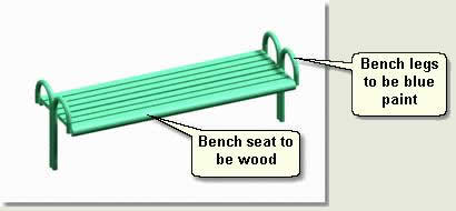
- Alter the Material IDs of the legs and seat as above, giving the legs a Material ID of 1 and the seat slats a Material ID of 2
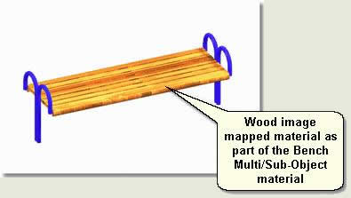
- Create a Multi/Sub-Object material called Bench with a standard none-mapped blue paint material for sub-material ID 1 and a wood material using CEDFENCE.jpg as the mapped image
- Assign Material to Selection and apply a UVW Map modifier to the bench. You will need to adjust the UVW Map modifier parameters to position the wood image map correctly on the bench seating
NOTE: Because there is only one map present in the Multi/Sub-Object material you can apply a UVW Map modifier to the whole object and it will effect the one map. When you assign a Multi/Sub-Object material that has multiple sub-materials containing maps, the UVW map modifier has to be applied to each element. Otherwise the modifier changes all maps on the object globally. Later, 'The Mapped Cube' explains how to adjust mapping on separate parts of an object when more than one map exists in a multi/sub-object material
UVW Map modifier Parameters. Change the Mapping to Box and Length, Width and Height to 1. Change the V Tile to 0.3
Rotate the Gizmo 90 degrees on the Z axis. This gives a convincing wood effect for the seating
TIP: Experiment with bump mapping and colour output in the wood sub-material for greater effect
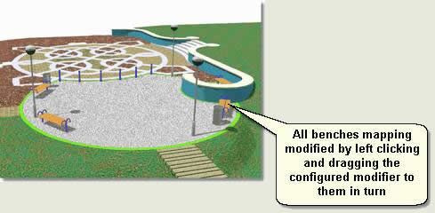
- Exit Isolate Selection and select all the benches
- Isolate Selection and assign the bench material to all the benches
- Select Bench 01
- In the Modify Panel left click and drag the UVW Map modifier onto the other benches in the viewport in turn. This instances the modifier to each bench and means you do not have to go through the process of adjusting the UVW Map modifier parameters for each bench. Now, if you want to tweek the mapping on one, the mapping on each bench will be updated
The following exercise deals with modifying maps individually on one object
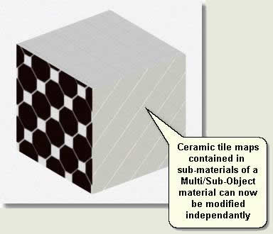
The Mapped Cube
This tutorial demonstrates the process for assigning a Multi/Sub-Object material to an object and then modifying the maps on different parts of the object individually. This technique would apply to the mapping of images of the sides of a building onto a model of building, for example. The tutorial does not use the current scene, but uses a box object to demonstrate the process. Most operations in the tutorial file have been completed and the scene is used mainly for demonstration purposes
- Open kf409_02.max. This scene contains a box (editable mesh)
- Select Box 01. In the Modify Panel look at the modifier stack
There are a number of UVW Map modifiers applied to the object. To enable modification of independent maps use the following procedure:
1. Create Multi/Sub-Object material and configure Map Channels
- Open the Material Editor and select Box sides material. This has already been created for this tutorial using ceramic tile sub-materials. Each sub-material uses an image map and so needs to be mapped correctly on the object separately. Notice also that the sub-materials have been named at the top level to keep track of exactly what part of the object the sub-material pertains to
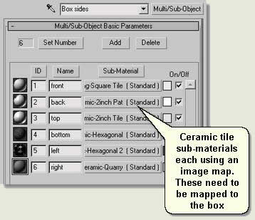
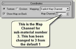
Open the parameters for each sub-material in turn and at the map level notice that the Map Channel number has been changed to correspond to the sub-material number
TIP: The Map Channel number does not have to correspond to the sub-material number (just the Map Channel number in the UVW Map modifier parameters). However, keeping these numbers consistent is a good idea
2. Apply a UVW Map modifier to the editable mesh, and then to independent polygon sub-objects
- Assign the Box sides material to the box
Notice in the modifier stack that a number of UVW Map modifiers have been applied to the box. A UVW Map modifier has been firstly applied to the whole object. Then, in element sub-object mode each side (polygon) has had a UVW Map modifier applied. After each application of the UVW Map modifier to each polygon the user has right clicked on the modifier in the stack and renamed the modifier so that they can keep track of exactly which part of the object the modifier is affecting
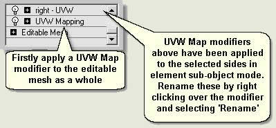
NOTE: This demonstration modifies mapping on polygon sub-objects (sides of a box). For objects such as benches and signs, element sub-objects are modified
3. Configure each polygon sub-object UVW Map modifier to work with independent Map Channels
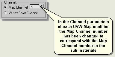
- In the Modify Panel select each of the UVW map modifiers pertaining to different sides of the box. Notice that under Parameters rollout > Channel the number has been changed from the default '1' to correspond with the Map Channel numbers in the sub materials pertaining to the sides (Step 1). The sub-material numbers have also been made to correspond for consistency (although this is not strictly necessary)
4. Modify each sub-material independently
- Select Box 01 and in the modifier stack select front - UVW. Change parameters such as the tiling and select the gizmo and move and rotate the map on the side of the box. This is now done independently
NOTE: Key Fundamentals does not carry this demonstration through to the current scene. However, this process can be applied to any mapping using multiple maps within a Multi / Sub-Object material
- List examples of where this technique would apply
Donate to CADTutor
If you found this tutorial useful, you might like to consider making a donation. All content on this site is provided free of charge and we hope to keep it that way. However, running a site like CADTutor does cost money and you can help to improve the service and to guarantee its future by donating a small amount. We guess that you probably wouldn't miss $5.00 but it would make all the difference to us.
Local Navigation
Wednesday
23rd April 2025
Sponsored Links
The Basics
- Dual Dimensions in a Dim…
- UCSICON Options
- "Best of" Basics: Irreg…
- Tool Palette Basics
- Original Dimension Value
- Possible Solutions to th…
- Avoid Using 'Standard' i…
- Shorten the Plot Scales…
- Update the Source File B…
- User Increment Angles fo…
- Drawing Information
- 'Sign Language'
- Rotate with the Copy Opt…
- Use the INSERT Osnap on…
- To or From the Current L…


