Jump to content

Search the Community

Showing results for tags 'weld'.

  • Search By Tags

    Type tags separated by commas.
  • Search By Author

Content Type


Forums

  • CADTutor
    • News, Announcements & FAQ
    • Feedback
  • AutoCAD
    • AutoCAD Beginners' Area
    • AutoCAD 2D Drafting, Object Properties & Interface
    • AutoCAD Drawing Management & Output
    • AutoCAD 3D Modelling & Rendering
    • AutoCAD Vertical Products
    • AutoCAD LT
    • CAD Management
    • AutoCAD Bugs, Error Messages & Quirks
    • AutoCAD General
    • AutoCAD Blogs
  • AutoCAD Customization
    • The CUI, Hatches, Linetypes, Scripts & Macros
    • AutoLISP, Visual LISP & DCL
    • .NET, ObjectARX & VBA
    • Application Beta Testing
    • Application Archive
  • Other Autodesk Products
    • Autodesk 3ds Max
    • Autodesk Revit
    • Autodesk Inventor
    • Autodesk Software General
  • Other CAD Products
    • BricsCAD
    • SketchUp
    • Rhino
    • SolidWorks
    • MicroStation
    • Design Software
    • Catch All
  • Resources
    • Tutorials & Tips'n'Tricks
    • AutoCAD Museum
    • Blocks, Images, Models & Materials
    • Useful Links
  • Community
    • Introduce Yourself
    • Showcase
    • Work In Progress
    • Jobs & Training
    • Chat
    • Competitions

Categories

  • Programs and Scripts
  • 2D AutoCAD Blocks
  • 3D AutoCAD Blocks
  • Images
    • Backgrounds

Find results in...

Find results that contain...


Date Created

  • Start

    End


Last Updated

  • Start

    End


Filter by number of...

Found 2 results

  1. ILoveMadoka

    Weld Display Issue...

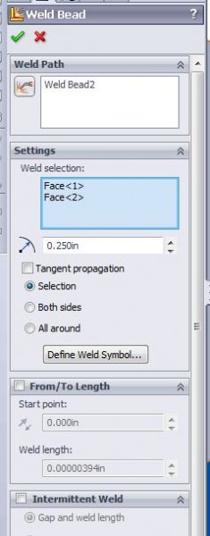
    (I am using SW 2013 per job standard) I placed a fillet weld between two pieces of metal and the weld comes in as a cylinder rather than a 90 degree representation like one would expect. I have tried all sorts of combinations in the settings with no desirable results.. Can anyone shed some light on how to get a more accurate representation for my fillet weld? There was nothing about this in the weldment exam!! Thanks!
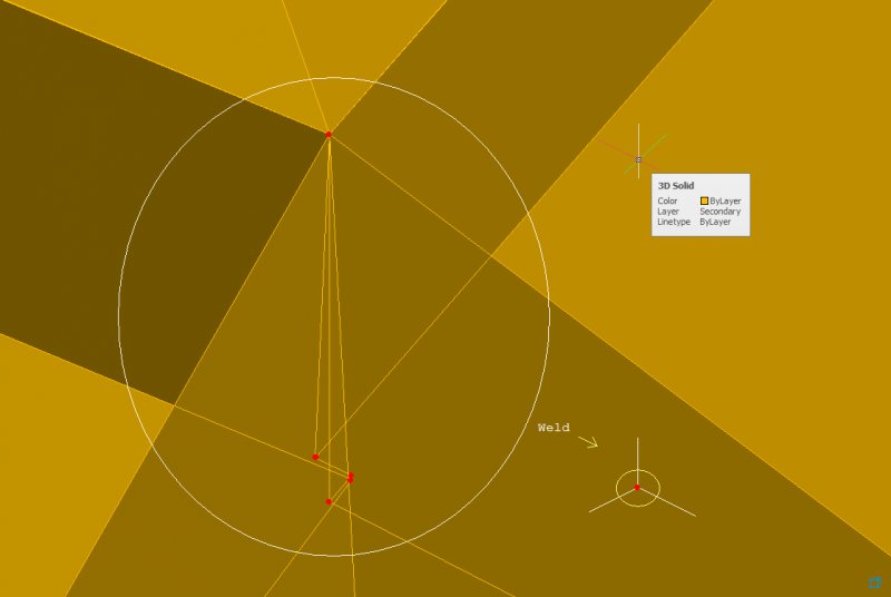
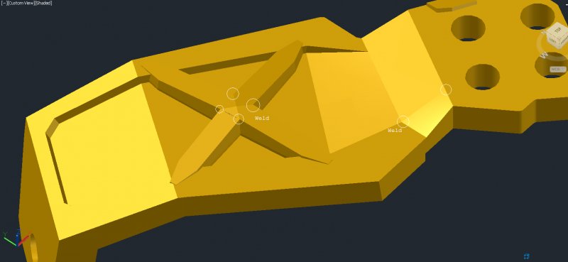
  2. Hello, I have a problem with artifacts in the 3D solid. AutoCAD didn't let me create perfect lofts because it has a restriction on every loft polyline having its vertices on the same plane. Thus I couldn't position them perfectly and they cut into the solid in places where I didn't want them to, creating extra edges and vertices. Since there was no way to fix that while lofting, I now have to try and fix it after the boolean operation. Here are the pics: Area to be welded: Overview. Above is close-up of one of the circled edges in screenshot below. So far I hear that I have to write my own script in C# to do this? I am OK with doing it, but does the object model even allow welding vertices? If not, i will be wasting time learning it.
×
×
  • Create New...