Search the Community
Showing results for tags 'symbol'.
-
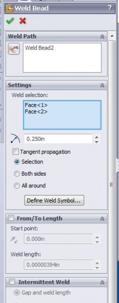
(I am using SW 2013 per job standard) I placed a fillet weld between two pieces of metal and the weld comes in as a cylinder rather than a 90 degree representation like one would expect. I have tried all sorts of combinations in the settings with no desirable results.. Can anyone shed some light on how to get a more accurate representation for my fillet weld? There was nothing about this in the weldment exam!! Thanks!
-
Problem copying drawing with ohm symbol into Word using Furix BetterWMF
sparklerach posted a topic in AutoCAD 2D Drafting, Object Properties & Interface
Hi All, We used Furix BetterWMF 2013 to copy our drawings from AutoCAD 2013 to Word 2007. Never had a problem till we upgraded to 2013 for both products. Now when we paste the drawing into Word (for our product manuals) any Ohm symbols turn into Question marks. I'm assuming the problem is not AutoCAD, as it displays correcty there. Just wondering if anyone else uses this product or has any probems with Ohm symbols in general in AUtoCAD 2013. Thanks -
I've never run across this symbol before. It is on a hand drawn (heaven help!) foundation plan I have been asked to redraw in a CAD program. On the left side is a 12"W x 24"D, Reinforced Conc. Turn down Slab. On the right side is 4" Reinforced Conc. Slab. with 6x6 1/10 WWM on 6 mil vapor barrier over crushed gravel. I am assuming it means there is a 1'-10" elevation difference between the two slabs, with the lower side on the left. Is this correct? Thanks! MichaelCAD
-
- hand drawn
- concrete detail
-
(and 1 more)
Tagged with:
-
Hopefully I can describe this clearly, here goes.. I have a face-based family that references an annotation family. I have already been able to shift create the annotation shift function, that allows the symbol to move independent of the 3D object (moving the annotation along a wall while leaving the 3D object in place). But now I need to add the ability to rotate that annotation as well (again, independent of the 3D object). This will be used for a camera device to simulate view direction of that camera. I have been able to figure out what is needed to rotate the annotation, but when I try to apply both the shift and rotate functions it over constrains the file. Currently, I have a ref. line that creates the shift function and another that creates the rotate function (both work independently from one another). But, since one of those lines is not always parallel to the other, I cannot lock one line to the other. What I seem to need is the ability to lock an end-point of a ref line / level to the end-point of another. This should allow the shift function as well as the rotate function I need. Does anyone know of a way to do this that I may be missing? Thanks,
-
Help me. I worked in a drawing(#1) a few weeks ago and since then have copy pasted the drawings to be scaled at 1 1/2" into another drawing(#2) and have since been only working in this drawing(#2). In the original drawing(#1), I was able to scale my drawings at 1 1/2" without any problems but in my second drawing(#2), when I try to scale drawings at 1 1/2" all of my annotative bubbles get ridiculously small. Once having discovered this, I copy pasted my second drawing'(#2) components into a 'Copy' of my original drawing(#1), thinking that my second drawing(#2) file might have been contaminated, but with no luck because I could see that within the Same viewport scaled at 1 1/2" the original drawing(#1) was scaled properly but the second drawing'(#2) symbols became very small. I am stuck. thanks.
- 1 reply
-
- scale
- annotative
-
(and 1 more)
Tagged with:
-
Hi guys, hopefully a pretty simply one here. I was just wondering if anyone has a routine (or knows of one) which will create a 'bevel' symbol/dimension similiar to the one shown in the attached image? Im not certain that im using the correct terminology to describe the dimension type - and i have tried a bit of googling with little luck (not knowing exactly how to describe what i was looking for). So... does anyone know of a routine which would create such a symbol? or of there is another method i can use? Thanks so much for any help.
-
I have started to attempt to learn DCL and am currently using VLIDE as code editor. But when I write a DCL code and click "Format edit window" it returns an error: If I execute the code it runs just fine ("Preview DCL in editor" works, too), but I can't get it to organize my text. Doesn't it work at all or am I the only one having difficulties? I have been searching this since yesterday and have found not a single person mentioning it, which means either one of two things: no one has ever had this problem before or it is so simple to solve that no one ever needed to ask in internet forums. Hope I'm not asking a stupid question here This is an example of code I am trying to format (copied from a DCL tutorial by Jeff Sanders): EXAMPLE : dialog { label = "EXAMPLE.lsp"; : column { : boxed_column { label = "column 1"; : boxed_column { label = "column2"; } : boxed_column { label = "column 3"; } } ok_cancel; } } Thank you all in advance! Felipe
- 1 reply
-
- symbol
- formatting
-
(and 3 more)
Tagged with:
-
I have done a fair amount of scouring the internet for a solution, to no avail, hopefully someone here can help me. For example, I have a hosted electrical receptacle device with a loaded annotation (2D symbol for printed plan purposes). What I would like to do is add a horizontal annotation offset that allows me to move the symbol left OR right based upon a single properties window field. As it sits right now, I have a reference line to one side of my device center line that is tied to a dimension parameter. Unfortunately Revit does not allow negative lengths, which means moving the annotation in the opposite direction is not possible. I have even tried (without expecting it to work) locking my annotation to two different reference lines (a right and a left parameter), but this produces no change at all. I believe this is because it can't be locked to two parameters, with different values, at the same time. One of the threads I read (http://www.revitcity.com/forums.php?action=viewthread&thread_id=15532) makes mention of this functionality, but does not go into detail on how to make this happen. Given that this thread was quite old, I did not ask this question on that forum yet, but I might. Any help you can give is much appreciated. FYI.. I am using Revit MEP 2011.
- 1 reply
-
- reference line
- parameter
-
(and 3 more)
Tagged with: