Search the Community
Showing results for tags 'sweep'.
-
We had a custom part needed to be fabricated, guy bent bar stock to desired shape, gave to me. Now I am trying to reverse engineer to get manufacturing drawings and try to figure out the best way to get a straight length. I created a 3d sketch and sweep on the line for the shape. I can measure the straight lengths and arc lengths, but is there a better way to calculate this? I tried doing as sheet metal so I could create a flat pattern, but with round bar it doesn't seem logical, also tried making square and then fillet the edges but that didn't work well either. There are bends at different angles and planes so I am thinking about this for future use of wiring. For example, if I run wires through points with a 3d sketch how will I easily calculate how much wire I used? Saw lots of old posts but no solutions, thought this would be a good one to discuss further. HYDROLIC CYL LEVER BAR2.ipt
-
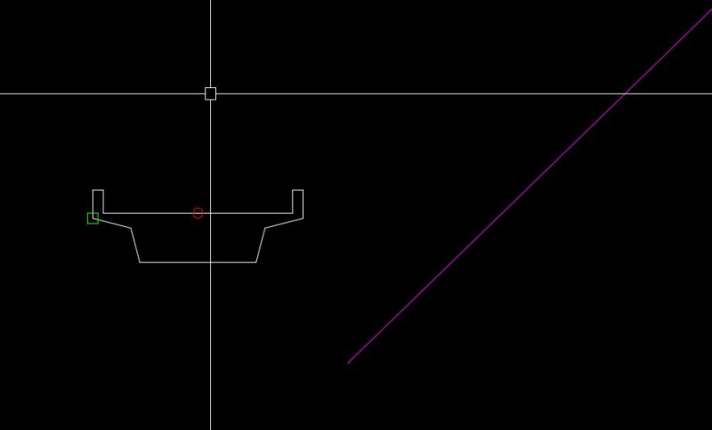
Hi I am having a problem with the SWEEP command. I have defined a 2d polyline profile which i want to sweep along a 3D polyline alignment. If I use a basepoint in the middle of the profile (red circle) the function fails, if however I use another point (green square) the command works. See attached .DWG. Bridge Model.dwg What am i doing wrong?
-
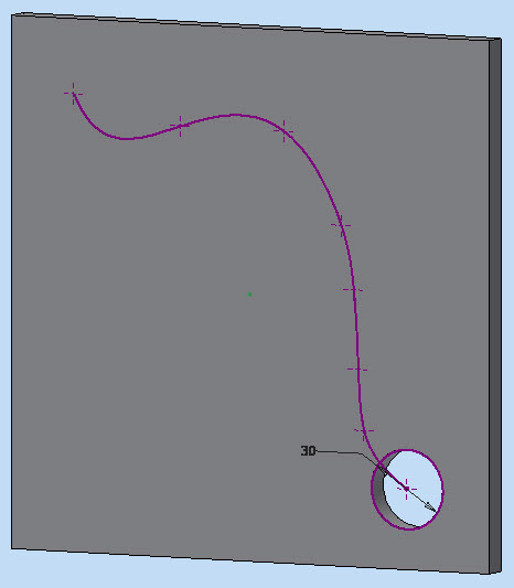
I tried slotting a plate along an irregular line by SWEEPing an extruded hole alone a spline No luck! Inventor 2015 does not select the spline as a path. I must have this wrong somehow but I cannot find any tutorial material that covers it. Can someone please tell me the right way. Thanks Page 15 Cam Plate.ipt
-
Hey I am a new user to autocad Inventor and already watched a lot of tutorials. So I really start to get the hang of it. Now i'm trying to make a barbecue design but I don't really find how to solve the legs. As you can see the ends have two different end angles. And how I can make this part one time and then divide it in two separate parts? It's mainly the sweep part I got problems with, the circular pattern thing I know how to do. How would u guys tackle this problem? Thanks
-
I am trying to draw an octagonal luminaire arm with a slight taper for a light pole by sweeping along a polyline profile. Sometimes it lets me do it, most of the time it doesn't. I can do a scaled sweep along a straight path and an unscaled sweep along a curved path, but I cannot do a scaled sweep along a curved path. I've spent hours on this and can't seem to figure this one out. What am I missing?
-
Can't seem to coincident-constrain two shapes on different planes
lizazelle posted a topic in Autodesk Inventor
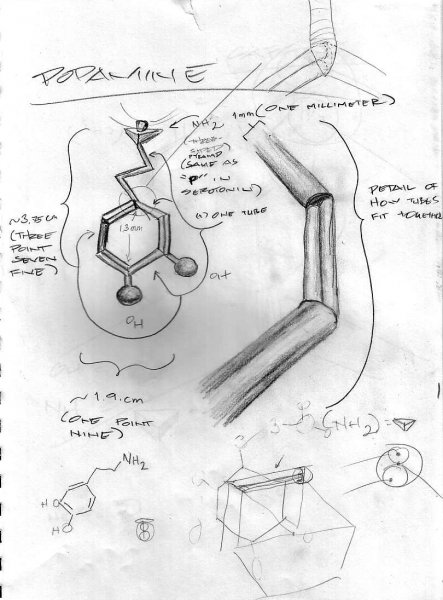
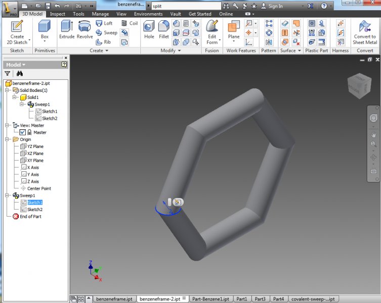
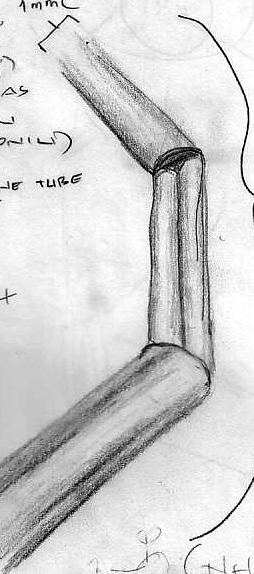
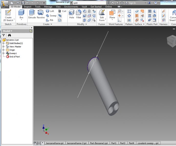
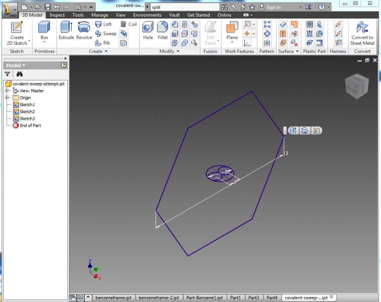
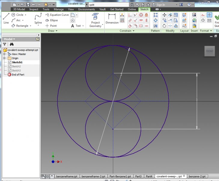
I am trying to make a stylized model of a molecule and having some issues. Here's the sketch of what I'm trying to create: So far, I've been able to sweep a circle around a hexagon-shaped path, which will create the single-bonds in the benzene ring in the finished product: I made a circle on the XY plane, then made a hexagon-shaped path on the YZ plane, did a coincident contraint on the center of the circle and attached it to the path and then did a sweep along the hexagon path. Hooray. Then I needed to create the covalent / double-bars on every other section. I figured I would create another hexagon-swept ring, but with all double-bars, and then cut and copy the bits of each together afterwards so it would look like this: I tried sweeping to faces, but it only gave me one segment, but it didn't work. So then I thought I'd sweep two circles around the edges of a square-faced sweep in hexagon form to end up with two rows, like in this example: So here's my attempt, but I can't get the edge of the square in the middle of the two guide circles to coincident-constrain to the corner point of the hexagon path (I tried "project geometry" to no avail, and it's turned on automatically): Here's the sketch of the face I'm trying to sweep: Not sure why it's not working this time around, and I might be going about this the wrong way... would love some help on this. Thanks! -
FLATSHOT not hiding obscured lines in swept solid
KCorby posted a topic in AutoCAD 3D Modelling & Rendering
I have a swept solid that FLATSHOT will not hide the obscured lines for. In the FLATSHOT dialogue box, I have tried all options, with different results. Does anyone know a setting that I can change or alternate method that I can use to get 2D geometry from this solid that I can use in my 2D drawing? Thanks! twisted_pair.dwg -
I'm having a problem sweeping a curved object over a spline. The object will sweep over a straight line...but not on the spline. I keep getting "unable to sweep object(s)" in the command line. I could be doing it all wrong... I've attached the file. Any help will be appreciated. WE ACAD.zip
-
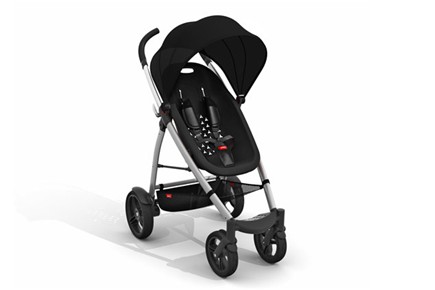
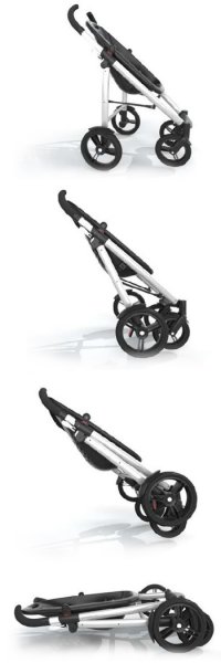
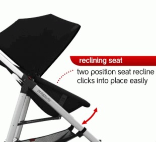
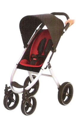
Hi CADTutor. I am new to this forum. I need some help on a project i'm currently trying to do and I have no idea where to begin. I am hoping some kind soul out there will show me the way.. I am fairly new to Solidworks but not a complete newbie. The main commands I know is the Extrude, Cut, Shell and other features. The bits I struggle on is the Sweeps, Reference gemometry, mates, and other stuff.. THe project i am working on is trying to make a pushchair/baby stroller in Solidworks. I have images of what I want to model, have the main measurements i need, i just to make it in Solidworks, Assemble and then test using the Simulation software... But i have no clue where to begin Someone please help! Images of the stroller push chair i want to model are at the end of the thread post. A breakdown of what I want to do: 1) I want to make the frame of the stroller + the wheels. With this assembled, I will be able to do an initial Displacement Test and check my Factor of Safety. 2) I want to make the seat and the Sunhood of the stroller. This will be added to the main assembly. 3) I want to make my Stroller have the ability fold, and the seat to be reclined backwards as shown in two of the images. Stroller's website: http://philandteds.com/products/push/smart By the way, I don't want to make the model using surfaces etc. THe main tool i need to make the frame and stuff is the Sweep. I am using Solidworks 2011 version. Thanks for reading, I appreciate any help that can be offered, Raz. Images of the Pushchair I want model: http://4.bp.blogspot.com/_pUw8FCLgav8/TR-t_-BjG1I/AAAAAAAAASA/riX1YaBq_30/s1600/phil%2526teds2.jpg
-
Hello, I am having trouble modeling a multi-layered solenoid in solidworks. The issue arises when I sweep a sketch around a 3D curve that describes my helix. Although the sweep is done as "follow path" the shape is produced correctly for the first turn after which it starts sloping instead of staying horizontal to the top plane like I want it to. Please let me know if you have any ideas on how to fix this. I cannot attach my file here but you can find it at this link :http://www.eng-tips.com/viewthread.cfm?qid=298129&page=1 Cheers, Sorin
-
Twister bulb - cant sweep along spline?
John Kimble posted a topic in AutoCAD 3D Modelling & Rendering
Hey, I'm pretty new to Autocad and I'm trying to draw one of those new energy-saving lightbulbs in 3D. It's a Phillips Mini Decorative Twister bulb to be exact. I'm trying to make it as accurate as possible. I have the base done and I did the spiral/middle part of the bulb, but I ran into a problem when I tried to do the bottom of the bulb where it meets the base. I used a spline since the bottom part of the bulb meets the spiral part at an odd angle, then curves at almost 90 degrees and goes straight to meet with the base. The problem is when I tried to sweep a circle along the spline Autocad wouldn't let me. If someone can help me with this or give me some tips on how best to do the bottom and top parts of the bulb, it would be much appreciated. Thanks. -
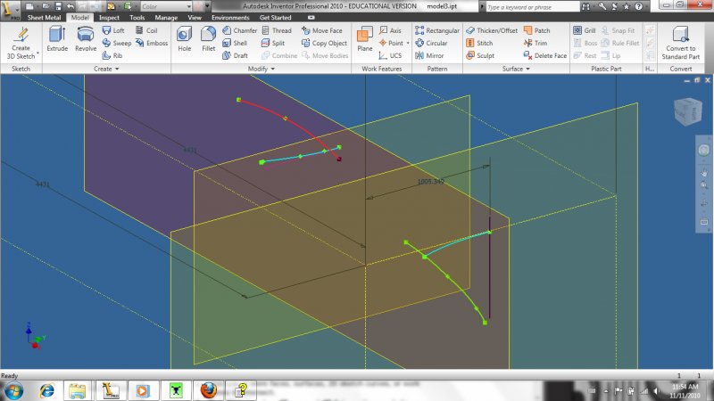
Hi all, A little new to inventor. Using inventor 2010. I am trying to use a 3d intersection curve to create a sweep. I want to use the 3d curve as the profile but am not able to select it. If the image works the two lines in blue are the 2d sketches that were used to create the 3d intersection curve and the red line is the path. The purple line is the 3d curve. Thanks in advance for any help.

