Search the Community
Showing results for tags 'stringer'.
-

Relatively Painless 3D Modeling of A Potentially Troublesome Unistringer
Dadgad posted a topic in Tutorials & Tips'n'Tricks
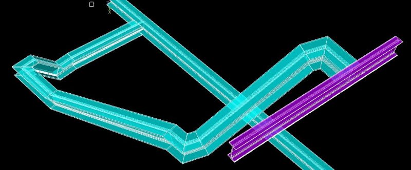
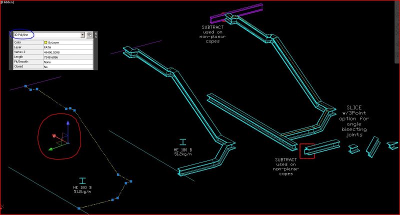
An architect friend, asked my assistance in modeling and creating fabrication drawings for a rather daunting unistringer to be made of HEB180 profile, which had been giving her trouble. I was happy to help, but I had some trepidations, as there are a few unorthodox angles evident in plan view. I was very pleasantly surprised to see how well the Sweep command handled this task. Had I needed to use the Extrude or PressPull & Subtract commands and manually align all of these bits, it wouldn't have been much fun. Pretty well defining the concept of, on the far side of Tedium. I started by defining the sweep path as the intended center of the top flange of the HEB180 specified, with a continuous 3D Polyline. Having chosen an isometric view and set the UCS to World, I accessed my closed polyline of the profile and put it into modelspace. There is no need to manually orient the Object to be swept into position on the Path which will be used for the sweep command, the software will take care of that. I started the Sweep command, defined the Basepoint as the top center of the profile (because sometimes the software guesses wrong), and picked the PATH. Lo & Behold, it worked perfectly, you could have bowled me over with a feather! I was surprised to find that I did not need to specify the Alignment, as square to the path is the default. On a subsequent repeat without specifying the Basepoint, exactly the same, no problem. Just pick and click would have done it, without any user input. Should you experience a less than satisfactory result without specifying, then Undo and try again with a specified Basepoint. The 3D Solid generated was a single piece, which would have been very difficult to document assembled. Using the Slice command with the 3Point option, in non Orthogonal views, it only took a couple of minutes more to cut it into the subparts, ready for me to Solprof for fabrication dwgs. The keys are creating an unbroken PATH, so that the model to angle bisector function will be called into play by the program; setting your UCS to World and using a CLOSED polyline if you are interested in creating a 3D Solid. In this case, that meant I needed to use a closed polyline for the object profile and a 3D Polyline to accomodate the elevation changes for my path. :wink: After slicing and dicing the 3D Solid stringer into the individual parts, I added the structural members to which it will attach, and the mating bits were coped into them with the Subtract command. I was quite pleased to not have to wrangle all those seemingly random bits, it clearly would have taken longer than the five minutes required to do it this way. It is always gratifying when something works much better than anticipated!- 10 replies
-
- stringer
- profile modeling
-
(and 1 more)
Tagged with:
-
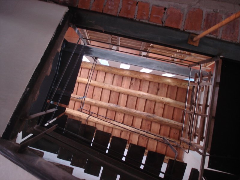
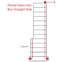
Any idea how to make a partial open (saddled) and partial box (housed) stringer? Hopefully the image can provide some clarification. The only difference is that the open treads do not extend but are the same length as the box treads. Using Autocad Architecture 2012.
-
- partial stringer
- open stringer
-
(and 2 more)
Tagged with:


