Search the Community
Showing results for tags 'mline'.
-
Hi All, I am trying to draw a pline by connecting all the vertices of the mline. Below is my code, but it gives an error saying; error: bad argument type: fixnump: (vl-load-com) (defun c:hl_mltopline () (setq mspace (vla-get-modelSpace (vla-get-activeDocument (vlax-get-acad-object) ) ) ) (setq ml (vlax-ename->vla-object (car (entsel "\nPick a multiline: ")) ) ) (setq coord (vlax-safearray->list (vlax-variant-value (vla-get-coordinates ml)))) (setq pl_points_safearray (vlax-make-safearray vlax-vbDouble pl_points_list)) (setq pline (vla-addlightweightpolyline mspace )) (entmod pline) ) Could someone please help me fix this? Thanks in advance..!!
-
Hello, Someone can help with the following: In a job I have different multiline styles. Using a routine will it be possible to toggle current style just picking on one of these multilines? Thanks Aalmeidah
-
MLine keep fill after explode
d1212 posted a topic in AutoCAD 2D Drafting, Object Properties & Interface
Hello Community, is there a way to keep the fill of a MLINE after I explode it? I'd like to have single LINES with a HATCH. Or is there a diffrent way to achieve this? I'd like to draw e.g. two lines with a solid hatch in between at once. Thanks and kind regards d1212 I use AutoCAD 2016 -
Can't Change the Justification and Scale of MLINE with VBA
biguelo posted a topic in .NET, ObjectARX & VBA
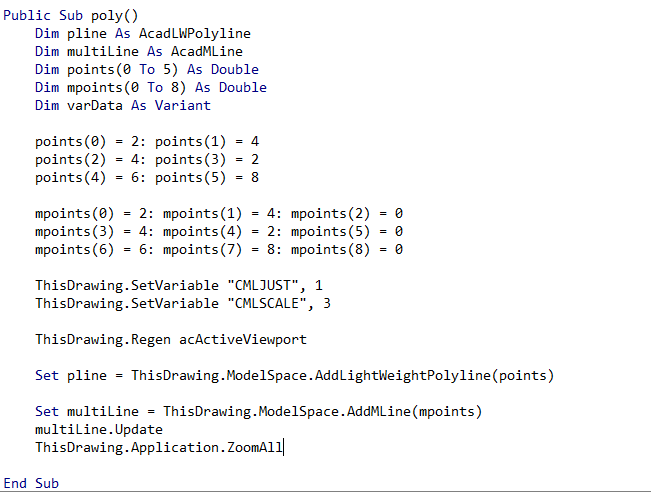
Hi, I'm trying to draw a MLINE using the vertex of a Polyline and that part of the macro works ok, but when I try to change the justification and/or the scale of the MLINE changing the system variables before drawing the MLINE, it doesn't work, I always get the same justification and/or scale. The strangest thing is that when I check the system variables in the command line they have the value the macro set but the MLINE drawn by the macro doesn't assume the new justification and/or scale. What is the problem? Using Autocad 2009 or 2014. Here is my code> Public Sub poly() Dim pline As AcadLWPolyline Dim multiLine As AcadMLine Dim points(0 To 5) As Double Dim mpoints(0 To As Double Dim varData As Variant points(0) = 2: points(1) = 4 points(2) = 4: points(3) = 2 points(4) = 6: points(5) = 8 mpoints(0) = 2: mpoints(1) = 4: mpoints(2) = 0 mpoints(3) = 4: mpoints(4) = 2: mpoints(5) = 0 mpoints(6) = 6: mpoints(7) = 8: mpoints( = 0 ThisDrawing.SetVariable "CMLJUST", 1 ThisDrawing.SetVariable "CMLSCALE", 3 ThisDrawing.Regen acActiveViewport Set pline = ThisDrawing.ModelSpace.AddLightWeightPolyline(points) Set multiLine = ThisDrawing.ModelSpace.AddMLine(mpoints) multiLine.Update ThisDrawing.Application.ZoomAll End Sub Thanks- 2 replies
-
- scale mline
- mline justification
-
(and 2 more)
Tagged with:
-
Hello, I've made one very useful tool. It's called MLINE SPLIT and you guessed what it does. However it doesn't work on first and second vertices (1 and 2 vertex), and that is real mystery for me. Why are these vertices so different than all the other vertices. Below is my VBA code: Public Sub MLineSplit() On Error GoTo eh Dim ent As AcadEntity Dim p1 As Variant Dim p2 As Variant Dim x As Double Dim y As Double Dim atst As Double Dim min_atst As Double Dim taskas As Double Dim atst_nustatytas As Boolean Dim dblVertices() As Double Dim dblVerticesCnt As Double Dim dblVertices2() As Double Dim dblVerticesCnt2 As Double Dim sset As AcadSelectionSet Dim perdavimui As Variant Dim obj As AcadMLine Dim obj2 As AcadMLine Dim varpnt As Variant Dim krd(2) As Double Dim aa As Integer Dim objEnt As AcadMLine Dim objEnt2 As AcadMLine ThisDrawing.Utility.GetEntity ent, 1, "Select MLINE: " p2 = ThisDrawing.Utility.GetPoint(, "Select the SPLIT point in MLINE: ") x = p2(0): y = p2(1) atst_nustatytas = False dblVerticesCnt = -1 dblVerticesCnt2 = -1 'randam artimiausia If TypeOf ent Is AcadMLine Then 'AcadBlockRef isrinkimas Set obj = ent 'ThisDrawing.SetVariable "CMLSTYLE", obj.StyleName For aa = 0 To UBound(obj.Coordinates) Step 3 'MsgBox Str(obj.Coordinates(aa)) & "," & Str(obj.Coordinates(aa + 1)) & "," & Str(obj.Coordinates(aa + 2)) atst = DistanceBetween(obj.Coordinates(aa), obj.Coordinates(aa + 1), x, y) If (atst_nustatytas = False) Then min_atst = atst atst_nustatytas = True End If If atst min_atst = atst taskas = aa End If Next aa Else MsgBox "Must select MLINE!" Exit Sub End If Set perdavimui = obj.Copy Set obj2 = perdavimui 'Exit Sub For aa = 0 To UBound(obj.Coordinates) Step 3 'MsgBox obj.Coordinates(aa) 'MsgBox obj.Coordinates(aa + 1) 'MsgBox obj.Coordinates(aa + 2) If aa >= taskas Then dblVerticesCnt = dblVerticesCnt + 3 ReDim Preserve dblVertices(dblVerticesCnt) dblVertices(dblVerticesCnt - 2) = obj.Coordinates(aa) dblVertices(dblVerticesCnt - 1) = obj.Coordinates(aa + 1) dblVertices(dblVerticesCnt) = obj.Coordinates(aa + 2) End If If aa dblVerticesCnt2 = dblVerticesCnt2 + 3 ReDim Preserve dblVertices2(dblVerticesCnt2) dblVertices2(dblVerticesCnt2 - 2) = obj2.Coordinates(aa) dblVertices2(dblVerticesCnt2 - 1) = obj2.Coordinates(aa + 1) dblVertices2(dblVerticesCnt2) = obj2.Coordinates(aa + 2) End If Next aa If ThisDrawing.ActiveSpace = acModelSpace Then If dblVerticesCnt >= 5 Then obj.Coordinates = dblVertices If dblVerticesCnt2 >= 5 Then obj2.Coordinates = dblVertices2 Else If dblVerticesCnt >= 5 Then obj.Coordinates = dblVertices If dblVerticesCnt2 >= 5 Then obj2.Coordinates = dblVertices2 End If obj.Update obj2.Update Exit Sub eh: MsgBox "Error number: " & str(Err.Number) & " . Description: " & Err.Description End Sub
-
So dealing with mlines specifically..I was hoping to insert a block specified in the code at the endpoints only.. Lee's been a huge help..actually just today helping me with the following to insert a block on everything but the endpoints, which is perfect for inserting ftgs! This potential code could help us to insert a point load/# of studs (a 4" solid square block) at the end of all beams/hdrs that we draw with mlines. This would be such a big help as I alone go through about 200 of these in a day..that could potentially be completed with 3 clicks..fingers crossed..Any help is appreciated. --------- ;;-----------------=={ Block At Vertices }==------------------;; ;; ;; ;; Inserts a Block at each vertex of selected Polylines, ;; ;; with the exclusion of start/end vertices ;; ;;------------------------------------------------------------;; ;; Author: Lee McDonnell, 2010 ;; ;; ;; ;; Copyright © 2010 by Lee McDonnell, All Rights Reserved. ;; ;; Contact: Lee Mac @ TheSwamp.org, CADTutor.net ;; ;;------------------------------------------------------------;; (defun c:BlockAtVertices ( / *error* _StartUndo _EndUndo _Insert _AngleAtParam doc block ss ) (vl-load-com) ;; © Lee Mac 2010 (setq block "endtick.dwg") ;; << Block Name (defun *error* ( msg ) (and doc (_EndUndo doc)) (or (wcmatch (strcase msg) "*BREAK,*CANCEL*,*EXIT*") (princ (strcat "\n** Error: " msg " **"))) (princ) ) (defun _StartUndo ( doc ) (_EndUndo doc) (vla-StartUndoMark doc) ) (defun _EndUndo ( doc ) (if (= 8 (logand 8 (getvar 'UNDOCTL))) (vla-EndUndoMark doc) ) ) (defun _Insert ( block point rotation ) (entmakex (list (cons 0 "INSERT") (cons 2 block) (cons 10 point) (cons 50 rotation) ) ) ) (defun _AngleatParam ( entity param ) (angle '(0. 0. 0.) (vlax-curve-getFirstDeriv entity param)) ) (setq doc (vla-get-ActiveDocument (vlax-get-acad-object))) (cond ( (= 4 (logand 4 (cdr (assoc 70 (tblsearch "LAYER" (getvar 'CLAYER)))))) (princ "\n** Current Layer Locked **") ) ( (not (or (and (tblsearch "BLOCK" (vl-filename-base block)) (setq block (vl-filename-base block)) ) (and (setq block (findfile (strcat block (if (eq "" (vl-filename-extension block)) ".dwg" "") ) ) ) ( (lambda ( / ocm ) (setq ocm (getvar 'CMDECHO)) (setvar 'CMDECHO 0) (command "_.-insert" block) (command) (setvar 'CMDECHO ocm) (tblsearch "BLOCK" (setq block (vl-filename-base block))) ) ) ) ) ) (princ "\n** Block not Found **") ) ( (not (setq ss (ssget '((0 . "*POLYLINE"))))) (princ "\n*Cancel*") ) (t (_StartUndo doc) ( (lambda ( i / e ) (while (setq e (ssname ss (setq i (1+ i)))) ( (lambda ( param end ) (while (< (setq param (1+ param)) end) (_Insert block (vlax-curve-getPointatParam e param) (_AngleAtParam e param)) ) ) (vlax-curve-getStartParam e) (vlax-curve-getEndParam e) ) ) ) -1 ) (_EndUndo doc) ) ) (princ) ) --------- (These two codes may be from Alanjt though not positive..maybe from a thread he referenced but have since lost that page..sorry!) (defun c:aaa () (vl-load-com) (setq *model-space* (vla-get-modelspace (vla-get-activedocument (vlax-get-acad-object)))) (setq obj (vlax-ename->vla-object (car (entsel)))) (setq c (vlax-get obj "Coordinates") i 0) (repeat (/ (length c) 3) (setq x (nth i c) y (nth (1+ i) c) z (nth (+ 2 i) c)) (vla-addtext *model-space* (rtos z 2) (vlax-3d-point (list x y 0.0)) 3.0) (setq i (+ i 3)) ) (princ) ) (defun c:aaaa () (vl-load-com) (setq *model-space* (vla-get-modelspace (vla-get-activedocument (vlax-get-acad-object)))) (setq obj (vlax-ename->vla-object (car (entsel)))) (setq c (vlax-get obj "Coordinates") i 0) (repeat (/ (length c) 2) (setq x (nth i c) y (nth (1+ i) c)) (vla-addcircle *model-space* (vlax-3d-point (list x y 0.0)) 3.0) (setq i (+ i 2)) ) (princ) )
-
Hopefully can find some advice on creating a linetype from the ANSI 31 hatch type (/////////) I've read the many posts about creating linetypes but just can't figure this out..So far Autocad just gives me an error when I try and use 1/2 of the code from ZIG ZAG linetype below. Below that is what I have thus far. Any help would be greatly appreciated..we use this all day long at work and was hoping to turn this into an mline so I could just pic a point a long a wall (only 4" walls needed) and drag along as needed. Thanks again! *ZIGZAG,Zig zag /\/\/\/\/\/\/\/\/\/\/\/\/\/\/\/\/\/\/\/\/\/\/\/ A,.0001,-.2,[ZIG,ltypeshp.shx,x=-.2,s=.2],-.4,[ZIG,ltypeshp.shx,r=180,x=.2,s=.2],-.2 ANSI31, ANSI31 //////////////////////////// A,.0001,-.2,[ANS,ltypeshp.shx,x=-.2,s=.2],-.4