Search the Community
Showing results for tags 'inventor'.
-
Hello All, I am new to inventor; I need to add 5/8" flexiable Banding around the bundle of Pipes, Passing through the Groove on buttom borad and around the pipe. How some please guide me on how i can achieve this. Thank you in advance. Sticks.ipt
-

3D Interactive Assembly Instructions - SolidWorks Composer Alternative
cadasio posted a topic in Design Software
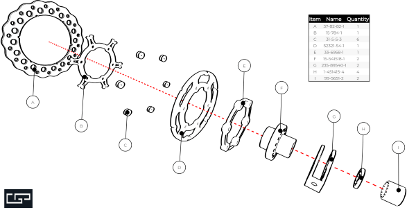
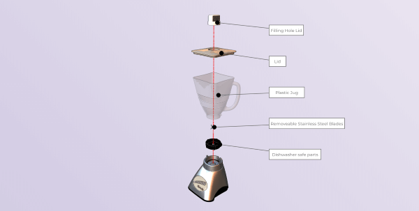
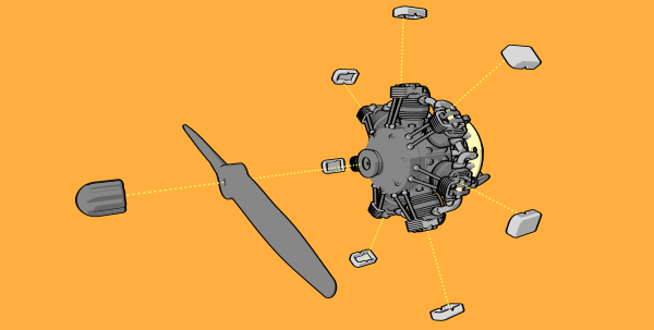
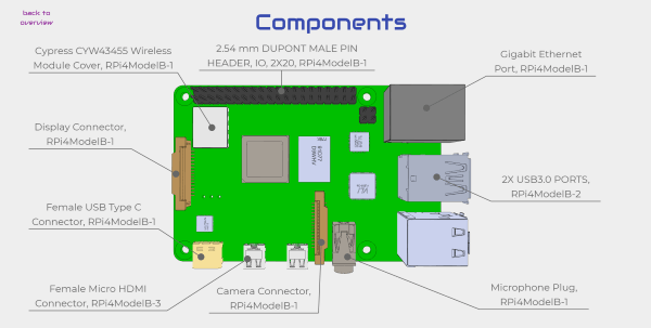
I thought it may be of interest to users of this forum that cadasio has just been released into early access and is available to use for free. cadasio is online software that will create assembly and service instructions, similar to those you may do with SolidWorks Composer (aka Catia Composer). However unlike SolidWorks Composer, cadasio focuses on creating an online project that you can share with anyone who has an internet connection, whether that's on desktop, tablet or mobile. We have plugins for the main CAD systems or you can upload neutral formats (STEP or OBJ). The projects are in 3D, so the end user can spin around and zoom in to get a greater understanding of your product and potentially reduce translation costs, and become more sustainable as you may not require lengthy paper printouts. Markup such as text, balloons, labels, pictures and arrows can all be added and well as hotspots and animations to make your products come to life and you can still save out 2D raster (png) images if you desire. Our showcase page has several examples to that demonstrate some of the capabilities of the software, and since its free why not come and try it out on your own products!- 1 reply
-
- solidworks
- inventor
-
(and 2 more)
Tagged with:
-
In Inventor, I wish to model a piece of metal. I wish to create a loft between two (2) sketches, and then unfold the item. I am having trouble and I need some assistance. Even though my sketch geometry had correct material thickness and bend radius, consistent with the sheet metal rule, the part won't unfold to flat pattern. Why?? -MR
-
Hi all, I'm new here. I've been learning Autodesk Inventor from you tube tutorials etc, so I'm certainly no expert. I wonder if someone can help me. I have been trying various ways to create a toothed detail around a curved surface. Nothing seems to work for me. I'm trying to create 2 separate parts that rotate and drop into each other, I need to cut/split along the line. The cut needs to follow to the centre point and not parallel with the centre line, which is the problem I am having. Hopefully this is explained properly. Thanks in advance for your help. Davie
-
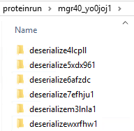
I'm not sure if this is limited to Civil 3D, or whether it applies to AutoCAD also. I'm starting to find that inside of user's %temp% folder, is a subfolder named "proteinrun", and inside this folder are tons of other folders, and inside each one of those, are more files and folders. On the few that I'm run across, there are thousands of files/folders sitting here, anywhere from 6-8 GB in total size. Ultimately, the files, when you finally drill your way to them, are .PNG files. I traced it back to Autodesk because of this KB article - which says it's related to Inventor, and that these files are deleted once Inventor closes. We are not using Inventor, and the files are not being deleted. I suppose it's possible that the files are not being deleted due to application crashing, but I was wondering if anyone else has run across this bloat?
-
Autodesk Inventor vs. Solidworks for Gun Modeling
GShocked posted a topic in AutoCAD Beginners' Area
Which would you recommend for modelling guns from 2D reference images? -
Newbie Inventor questions about folds and bends mostly.
Elforbo1987 posted a topic in Autodesk Inventor
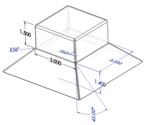
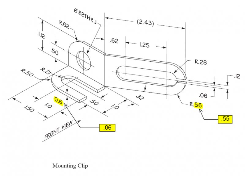
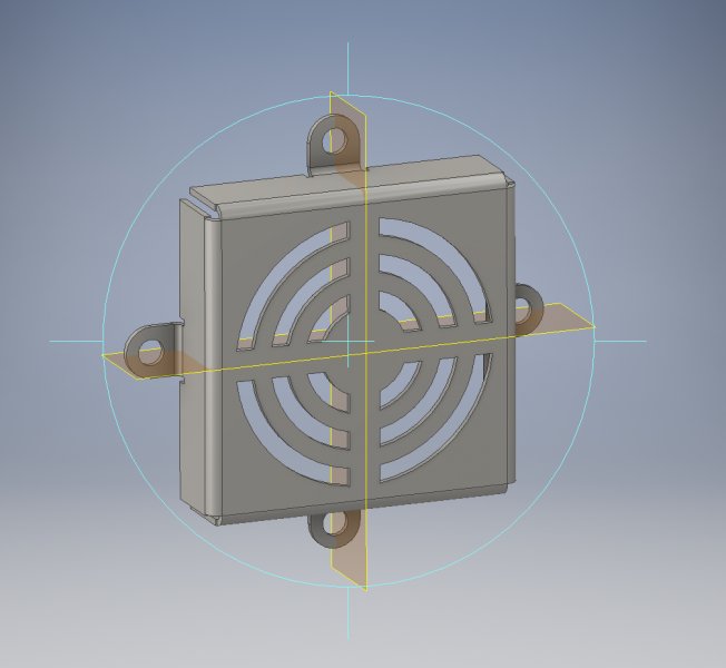
So i am in an inventor class and my teacher assigned the three drawings i attached below. 1.) How would i go about drawing this? There is no assigned thickness. I'm not sure what the height of the bottom pyramid shape is. I tried 1.4 at 45 degrees and that didn't work. 2.) My main problem here is that the folds or bends do not look the same. In the picture the fold or bend line is a single strait line for the long vertical piece going back 32 degrees, not a wide bend shape with 2 lines which is what i get. And the flat horizontal piece on the left has a straight 90 degree bend on the inside with what appears to be a rounded edge on the other side. Can you bend something to have that flat 90 degree corner in Inventor? Or would you have to cut to get that? 3.) Finally the fan cover. I did this drawing and everything came out great except the little flanges for screws are not flush with the back of the fan cover. It should all be flush on one level but mine stick out some raising it. How can you make the screw pieces flush? Thanks for your help. Sorry it's a lot all in one post.- 10 replies
-
Convert spline to line
gegenytibor posted a topic in AutoCAD 2D Drafting, Object Properties & Interface
Dear All, Do you have any idea how can I convert this type of spline to a "normal" line? I think I get it from Inventor or Mechanical... I cant explode or extend, or add chamfer. Totaly useless! Please help if you can! Thank You! T line.dwg- 3 replies
-
- mechanical
- line
-
(and 3 more)
Tagged with:
-
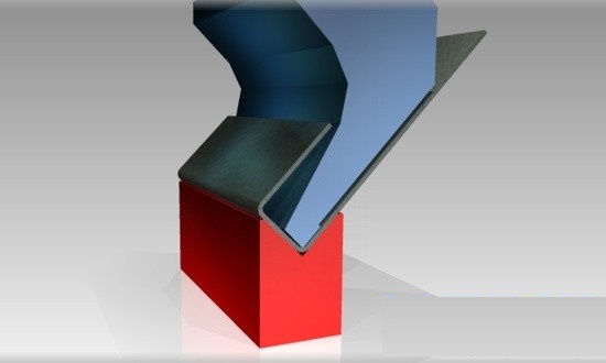
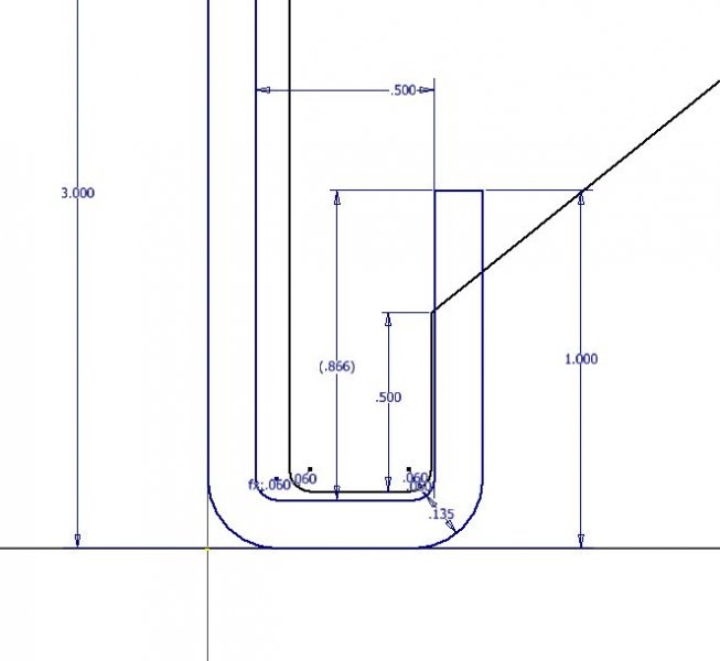
Started doing a bunch of sheet metal bending and trying to streamline our process. We have 50+ dies all labeled and organized on a rack, but at my computer we don't have reference to these dies other than the bend radius. My thought is that if we measure them all and make models we would be able to check to see if the die will clear the bend. Is there any smarter/faster/easier way to do this in inventor through the sheet metal bending tab or punch tool? This question came up when I made a part to get bent, see example image, but the die relief clashed against the part on the double bend. Rather than make a new die to fit my dimensions I have to redesign to fit our existing die parameters, ie make the lip smaller so the die clears. The hard way would be to just make a spreadsheet of the dimensions and verify the clearance, but I want something a bit more intuitive for future use. I think solidworks had something like this but I only used it at school years ago. Any fun suggestions? Thanks!
-
Hi Folks I am working on a project (in Inventor and using assembly) that requires me to constrain to or join to a surface profile that consists of two intersecting arcs, which have been extruded. I am trying to use the tangent constraint to attach a follower to the external edge of a figure of 8. I have drawn and extruded the figure of 8 into a solid using intersecting circles, arcs and lines joined with tangents. However, when I drive the parts, the follower deviates from the outer profile at the tangent points and follows the predicted path of the arc on which it was started, rather than moving onto the next arc. I have experimented with an egg shape, and a disk cam profile, (created by using different size circles, joined by a line, from and to tangent points) but the follower still deviates from the outer profile at these tangent points. Any ideas? Regards Tim
-
Hi everyone i'm having issues on applying a decal on an inclined surface using inventor here's a screenshot to let you understand my situation. Using the decal tool I cant select the surface on where i put the image (the selected one, to let you understand) Thank you for the help
-
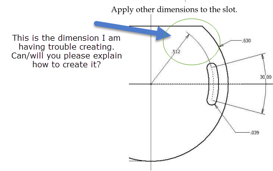
I am learning Autodesk Inventor and am having trouble adding a certain dimension to a slot to a product I am embedding into a 2D sketch. Attached is a screenshot that portrays the issue I am facing. Thank you in advance for your assistance.
-
Working with a company that does not use the vault. They have 1000+ parts and 200+ assemblies. If the vault is installed, activated, how easy is it to upload all and have them work and not break relations and constraints? The last time I started vault from scratch and didn't upload any old files. Will this be as simple as I hope? I really want them to get the revision management and copy design implemented into everyday use cause it's awesome. Thanks!
-
How to export harness to CST (computer simulation software)
pcsen20 posted a topic in Autodesk Inventor
Hello I want export harness file from Inventor to CST for EMC simulation, but CST import nastran file (*.nas) and step ap212 (*.kbl) file format, so I must save my harness in *.nas or *.kbl format. but I can't export these format. please help me to solve my problem. thanks -
hi to everyone, You will find attached a txt file which contains coordinate points from a naca that i created with qblade. I want someone to help me with creating a program at inventor's api that will read this txt and then transfers the content to an excel file. thank you in advance Blade.zip
-
Hi I have been learning inventor 2015 for a while now but would like to learn how to start calculating torque in dynamic simulation. I have looked at many different forums and tutorials but cant find anything that shows me what i need to know. What im trying to do is work out the torque needed (from a motor) to spin a disc. I have done a very simple assembly with 2 vertical posts with a disc mounted between them. i want to calculate the torque needed to spin the disc. I want to try different size and weights of disc to see how it effects torque and what size motor would be needed to spin the each disc. Any help or advice appreciated.
- 1 reply
-
- inventor
- dynamic simulation
-
(and 1 more)
Tagged with:
-
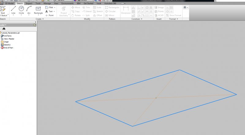
OK, It's more complicated than that... I'm working through a tutorial on linking parameters to an Inventor part. I have a spreadsheet set up to drive a regular box shape. My parameters are WIDTH, LENGTH, and HEIGHT. I am in the base sketch where I'd like to set d0 and d1 to WIDTH and LENGTH respectively. How do I find the two existing parameters please? I have looked both in the sketch and out on the workspace. If I try to add a dimension, it comes in as d3. The gentleman doing the video just magically clicks on the edge of the rectangle and d1 appears, ready to be edited. TIA Bill
-
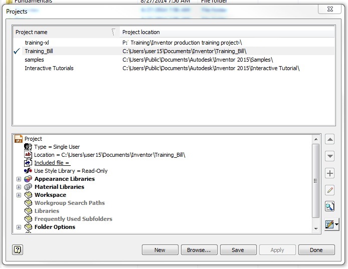
I'm going through a nice set of tutorials. I feel like I got through the 2D and Part modules well and picked up a lot. Now I'm getting into placing and constraining part in assemblies. There is a clamp that looks like it is part of this tutorial and an Autodesk tutorial. It deals with assemblies and constraints. I thought I'd take a look to see if it was located somewhere in my Inventor deployment. I didn't find what I was looking for, but I did find some other examples. I closed all of my open Inventor files. I selected the OPEN command. In that dialogue you can find a PROJECTS button. There you can create your own training project and browse other projects. There is a sample project located in my deployment. It looks stock.
-
Hi! First of all, This is my first post here and I'm not an EXPERT in english, so I will try to explain as good as possible. I'm using Inventor 2012 and AutoCAD Mechanical 2012. In Inventor I have a piece in which it was applied the punching tool (Custom one) it works Perfectly, but when I export it to autoCAD it comes with too many points or vertex, I know if I draw it in autocad I wont have that problem, what that's why we use a Punch Tool, to simplify things and get things easier and always the same. Re-draw is out of the question, unless its the ONLY solution.. We use two CNC Plasma Machine, one of them uses the Software CamBAM and it can edit the vertex and simplifies it and jobs done, but it cant export the job to .dwg or .dxf.. and the second and new machine (the one i'm having trouble) uses FastCAM software, it has something similar to adjust the vertex but, the real problem is within the FastNEST.. Either way, the best solution is to fix the drawing in autocad. EDITPOL doesnt work, as it just joins it, I need to make less points.. I could Upload the file if needed. I'd Really Appreciate any help given. Thanks and Again sorry for my many typos.o:)
-
hi, I've got a small problem; on the attached jpeg you will see a housing (shown in black) and a pipe inserted from underneath. how can i trim the material (of the inserted pipe) so that its flush with the hole in the bottom of the housing i.e. so nono is visible when looking through the housing)? somebody please help! Thanks Ben
- 6 replies
-
- remove material
- pipe
-
(and 2 more)
Tagged with:
-
Hello internet, Chelsea here. So for my graphics assignment I am making a lego character (to be specific Unikitty from the Lego Movie). I'm going pretty well so far, but I want to rotate the head along the neck in the assembly so that it isnt as straight as it is right now. Maybe like a 30 degree turn from where it is so it looks like it is looking to the side (not fully) instead of straight ahead. HOW? Thanks! Also, this assignment is due in two days *facepalm*
-
Dear Forum users, I am working on a project in which I need to show all possible motions of a vessel. I now made multiple positions using the "positional representations" option in the model in which constraints get an override. Although this is useful we want to see all possible positions in between the 2 outer positions that may occur (all steps in between need to be verified.). I have searched the web and found nothing to indicate such a possibility in Inventor. However I have found something that almost exactly describes what I would like to do in Inventor. Unfortenatly the example I found is in PTC-CREO see link: https://grabcad.com/questions/tutorial-how-to-create-motion-envelope-model-with-ptc-creo-parametric-from-mechanism Does anyone have an idea how to accomplish this in Autodesk Inventor? Best regards, Rody
-
- motion constraint
- inventor
-
(and 1 more)
Tagged with:
-
Easy way to associate materials with layers?
Watson posted a topic in AutoCAD 3D Modelling & Rendering
Hola! Sorry if I'm posting this in the wrong place... I did search for this before posting, but didn't see anything relevant. First of all, I'm an AutoCAD guy. I only know enough about Inventor to be very dangerous. At the company I work for (manufacturing) the Design team (me) uses AutoCAD to create our space planning blocks. This is pre-sale activity. The Engineers model everything (post sales) in Inventor. Occasionally I will be asked to draw something that is "just like that other thing we did," so I will open up Engineering's model of that thing and export to DWG to use from there. For rendering and quoting we use a 3rd party software that manages information via layers. For example, a work surface face is on a specific layer, the edge is on a specific layer, the powdered components are on a specific layer, etc, etc... When I export from Inventor, the DWG file is VERY detailed, down to the screws, but everything is on the "0" layer. This really sucks because I have to spend a ton of time dissecting the block in order to assign the correct layer information to every bit of geometry. I noticed the other day though, that when I switched to a realistic or conceptual visual style, the freshly exported Inventor block retained all the sweet info... like it was showing details down to the grain direction of the surface. My question to you guys, is if you know of an easy way to get that info converted to layer? Whether that be in CAD after I export or from within Inventor in my export. Ideally there's already an LSP or something similar that can do this in a button press. -
Hi, Does anyone know how to turn the visibility of the planes off I tried going to object visibility put it is not any of them? thanks
-
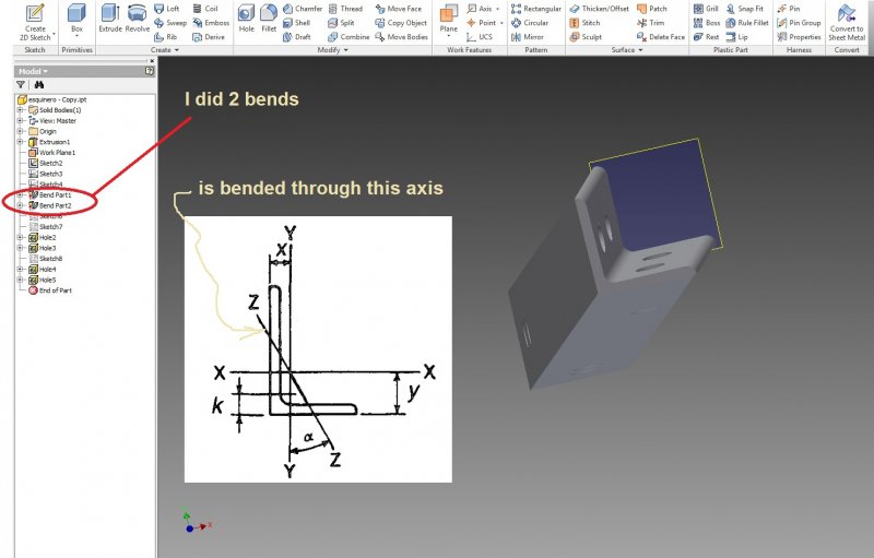
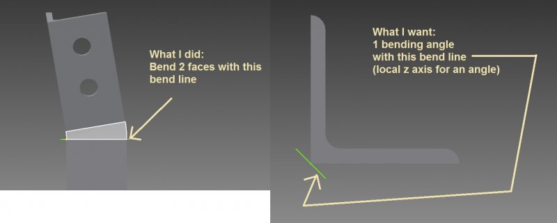
Hello I have a question, I need to bend an angle on its heel, I already did it, but whati did is to find the angle component on one face and then repeat it on the other face. But what I want is to use its local Z axis as bending line so that I use only one value and manipulate this value. How do I have to draw the banding line to do that, I have tryed it without succes, any recomendation?. Here I attach some pics, thanks


