Search the Community
Showing results for tags 'intersect'.
-
Version 1.0.0
2,557 downloads
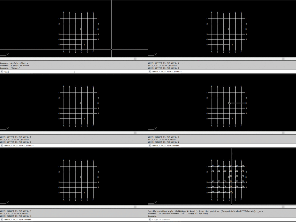
This lisp label block intersect point between plines. Date create: February 2020 Lisp start with command: Int . At line 103 change try2 with your block name The lisp work only with plines, 1.Select pline 2.Write which letter is the line 3.When you are ready pres ENTER 4.Select line 5.Write which number is the line 6.When you are ready pres ENTER -
Hello i have some problem with intersect point. I will upload dwg file. I dont know why when i try to get all intersect point from the red something go very wrong. I need all intersect point from the red lines. Thank you Try_5.dwg
-
INTERSECT command for more than two regions?
eyeofnewt555 posted a topic in AutoLISP, Visual LISP & DCL
Hey guys! If I had 3 regions like the picture, I'd like to be able to get the 2 intersecting regions (without doing them separately). Right now, I'm just getting errors Side request--a LISP that uses INTERSECT without deleting the original regions (similar to this lisp for the SUBTRACT command, or this lisp that does it for polylines rather than regions) Thanks! -
dynamic block intersection when changing angle
mvrp350 posted a topic in AutoCAD Drawing Management & Output
Hello, I'm having a hard time finding the solution for my problem. I want to create a dynamic block in Autocad 2014 In this block I need to determine the intersection between 2 lines. In the sample you'll see my problem. I want to make A, B and C variables in my block. The angle on top is always 90 degrees. With this information I can draw everything, but I don't know how to make the intersection properly, and keep it clean when manipulating the variables. Variable A has to be positive between 1 and 89 degrees, there are no restrictions on the variables C. Any help is much appreciated mvrp350 intersection problem.dwg-
- intersection
- intersect
-
(and 3 more)
Tagged with:
-
subtract command not working like expected after import
jcc5018 posted a topic in AutoCAD 3D Modelling & Rendering
Hey guys, I am working on a project where I am attempting to design a pendant. I wanted to do this in solidworks but I am not as experience with that and I'm having issues, so I went to what I know, AutoCAD. Unfortunately I am still having problems and I think it has to do with the import file from Adobe illustrator. What I have is a circle with different parts and block text that I would like to cut out. I saved the illustrator file to a dwg file and it imported with a hatch over all the solid areas. I deleted that to get the respective outlines, and extruded. Most loops extruded but some failed to do so for some reason. But I have an option to convert to a pline, but then I get a specify precision dialog which adds a bunch of points along what seems to be a straight line. Anyway, when I do manage to get things extruded, and go to perform the subtract command (or intersect which would be faster) I click the main shape, and then click the items I would like to remove, but it doesnt do anything. I have no idea what the problem is. Does anyone have experience with this? I did get one whole to subtract, but I really dont know the difference between that and the others that made it work. (P.S. If anyone has experience with solid works, I imagine this would be the same process. But I can get the outlines to appear, and extrude the outside shape, but I can't figure out how to get the inner holes to cut out.) Unashamed2.dwg -
I have two locations marked by steel stakes on my land that are also shown on a CAD drawing. The CAD drawing is two dimensional; however, contours are shown. I have physically measured distances between these two known points and numerous other locations that I wish to plot on the CAD drawing. I could always print the CAD drawing to scale and plot the new points on the CAD printout by using the two known locations, a compass to draw arcs and locating the new points by where the arcs intersect. I am sure there is a much more efficient way to plot these new points within the CAD program itself. I have just started to use CAD; any help is appreciated.
-
is there a good way to "snap" connect centerlines in a drawing, or a way to trim or extend them to the next centerline. There doesn't seem to be a good quick way in Inventor 2011 - weird - am I missing something my scenario is - I have a 90 degree elbow with some straight tangent ends- to which I've inserted centerlines to the elbow and thru the straight sections. I need to dimension from the center point, on the backside of the 90deg arc, to the face of the straight end. I can do that, but I have to use "intersect" for the centerlines instead of just having them "intersected" already


