Search the Community
Showing results for tags 'how to'.
-
Multileaders and Layout Space Text Height
dal-designs posted a topic in AutoCAD 2D Drafting, Object Properties & Interface
We're looking at implementing multileaders instead of quleaders in my office, and so I've been tasked with figuring out how to do it (being as I am the least senior, most peon-ish person in my department). I've messed with them before, so I mostly have it figured out. There is one thing that eludes me- despite much Googling and AutoCADding for Dummies and (the most worthless of all) AutoCAD's F1. My question is: when mleaders are annotative, where do you set the 'paper space text height'? I know I can change the model space text height (among other things) through Properties, but that seems to defeat the purpose of having annotative properties.- 1 reply
-
- how to
- annotative text
-
(and 1 more)
Tagged with:
-
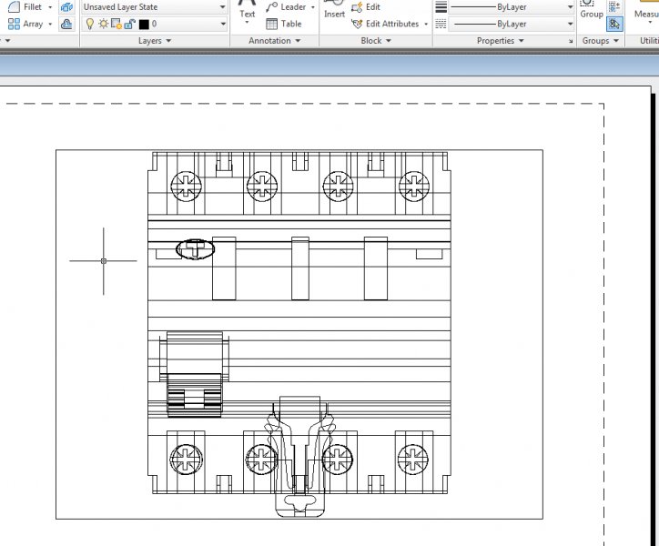
Hello All, Here in my office (oil and gas facilities planning) we're looking at revising some of our CAD practices. One of these involves drawing certain blocks that describe machinery (pumps, motors, gear boxes, loading arms, etc) so that when they lay over each other on plan drawings, you don't see wireframe bleeding through from the blocks underneath. In the past, drafters have exploded and trimmed these blocks to get the right look, but that way (obviously) lies madness. I am toying with the idea of adding a masking solid shape into each block to mask the parts that lie beneath, but how to best do that I don't know. It would be nice to just draw a filled solid PLINE shape that plots white (that is, doesn't plot on paper) but I can't figure out how to do that. There's also the solid option, but I don't like that much because you can't draw them with true, smooth curves. So how would y'all tackle this? All I can think of given the above constraints is to create pre-trimmed versions of each block, since our pump assemblies tend to go together only a few different ways each time, almost without exception...
-
Hello I have found a 3D drawing on the internet. but i want to print him in a realistic view from the top. this is the place where i have found it : Site like you see on the site ,an example of the 3d cad drawing in realistic colors,shadows, ... : but when i download the 3d autocad file i open it , and i can only print in this view: no realistic view, now is my question, is it possible to download the drawing from the site ,and print it in a realistic view ? ps: Sorry for my bad English
-
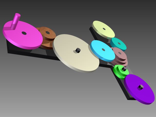
How do I do gears in Inventor 2011? I've found the spur-gear option under the design "tab". But then I get some problems... I've tried to turn my current "wheels" (see picture) into gears, but that don´t seem to be the way to do it. I also tried using component instead of feature, and then I get them to rotate however the gears collide. I don´t know how to solve this or how to do this properly.. Any help is appreciated. //André