Search the Community
Showing results for tags 'help wanted'.
-
Hi, I'm trying to make a mecanum wheel for a robot. I have trouble understanding what affect a roller length. I have 2 wheels, same ish diameter, same ish shape, same number of rollers but one of them has way less space than the other. My goal for now would be to have roller length between the red and white wheel. https://imgur.com/a/kJR5H41
-

Prewritten Lisps and Acad Commands Combined for .dxf Import
KraZeyMike posted a topic in AutoLISP, Visual LISP & DCL
Almost every drawing I work on is exported from another Survey program and then Imported into Civil3D as a DXF I have sped up this process with a Lisp command and built in AutoCAD functions but would really like to combine the whole process into one Command. I am not sure if I can modify and combine existing lisps to achieve this or using a Script which I have had no experience with as yet. Below I have outlined the steps, attached the Lisp used and a video (two parts due to size limit) outlining the process that for every job is becoming tiresome. Redefine the inserted Block For some reason when I insert the DXF it does not automatically redefine (Which is needed to update Survey blocks to my custom Acad Blocks. So I have to re-insert the DXF to force redefine "DP" Lisp (Attached) - This routine deletes the crosses that are carried over from our Survey Software and are not required. Explode and set "By Layer" Color, Linetype and Lineweight Attsync two blocks - POINT_CROSS and $FILL Finally I would like to select the Attsync selection (POINT_CROSS and $FILL) and set their scale back to 1 Seems to be that these blocks which I have redefined to be annotative, scale according to the model space when inserted which we don't leave on 1:1 but our most commonly used scales for each template. As always the expertise and help provided here is greatly appreciated. Part One - DXF into Civil3D.mp4 DP (Delete Points).lsp- 6 replies
-
- help
- help with lisp
-
(and 2 more)
Tagged with:
-
Pizza! My block is a simple arc that can be swept around a circle and retain an enclosed area, like an adjustable piece of pizza. It works fine as long as I drag the grip, and mostly the input works too but there are certain sequences that mess it up, going past 180° mainly. Drag it to 90°, then type 340, it makes a concaved arc with a 20° fill, not 340°. At this point I have to do some undos because all input now makes a V with a huge bulge except back to 45° sometimes, well, I am including the file so you can see. I have lots of constraints to keep any of this from happening, there are no over-constraint warnings. The original horizontal line from 0,0 to 1,0 is constraint locked, but it can flip to -1,0 if done in the right (or wrong) sequence, the arc is inverted to a pline and constrained concentrically to a circle (on a different visibility state-off). I have learned over the years how quirky dynamic blocks can be, but some of them take so long to debug, it negates any time I'd save by just using multiple blocks, like many times over. Eventually I would like to put a polar array of slice cutlines every 30°, a nightmare of its own, tried it already, ugg. Please debug this somebody! Thanks much! R.L.Hamm Pizza Dynamic Block.dwg
- 1 reply
-
- help wanted
- dynamic block
-
(and 1 more)
Tagged with:
-
Im interning for a medium sized company and I was tasked with creating a new file structure and naming system for our engineering files. I was wondering what are the best ways to name CAD files so that they are easy to find and make sense. Thanks you all your help guys. I really need it. Also we use both auto cad and solidworks to make mostly large metal parts if that makes any difference
- 17 replies
-
- help me
- help wanted
-
(and 3 more)
Tagged with:
-
Hi this is my first autocad 3d project so forgive me if I am not using the right terminology. So I need to create a boxed shape cover for an instrument that we have. So I drew the base in 2d then used the extrude command to build the box, after that I used the shell commands to empty it, now I am stuck at trying to remove the bottom of the box. Can someone help please?
- 2 replies
-
- help wanted
- box
-
(and 1 more)
Tagged with:
-
Probably a dumb question, but I need some help.
KAnderson09 posted a topic in AutoCAD Beginners' Area
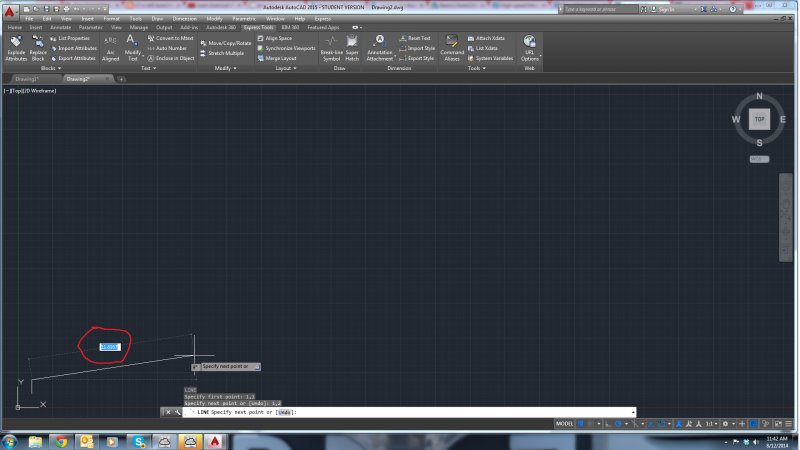
This is my first ever attempt at learning AutoCAD and I'm having some issues. After I've chosen the starting points for a line, a box shows up and I'm not able to access the command line unless I enter something into it. E.G. 12, As soon as I hit that comma the box disappears until I plot my next point. Its incredibly inconvenient and I was wondering if there was any way to shut that option off? Thanks for your help. -
New to AUtoLISP, trying to insert a block and rotate it
GigaFHLS posted a topic in AutoLISP, Visual LISP & DCL
Hello, I'm very new to Autolisp, and I am having some trouble with my code. Here's a description of what I am trying to do: I have a drawing consisting of two pipes, bottom pipe and upper pipe. They will be inclined in reference to the paper, represented by the square. I need to insert at the end of these pipes a block (inside the block will be a leader), which then will be rotated to align itself with the paper orientation. Somehow, the code i've written so far is not working, I believe it's because i'm not getting the correct syntax of the commands i'm using. Would anyone be willing to take a look? Help is much appreciated. See attached files for my code and the drawing (containg the desired block) ttten.LSP Drawing1.dwg- 3 replies
-
- lisp
- help wanted
-
(and 1 more)
Tagged with:
-
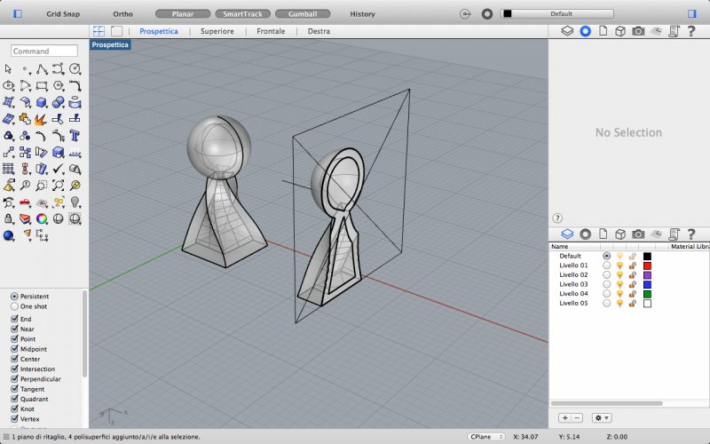
Hello! I'm a noob in rhino and I found some problems by making a polysurface solid: my problem is that I have two elements: a sphere and a twisted pyramid, joined by boolean union which I can't offset to add an internal thicken. when I do it (with "solid" option activated) it just creates a polysurface inside it, without creating an emptiness in it. I can't even make a boolean difference, boolean 2 objects or neither a solid subtraction that work with polysurfaces which surfaces do not intersect each other. Indeed, when I make a section to see how it is inside there's no hole but only the sectioned edges of the offset polysurf. H E L P!!!!
- 3 replies
-
- polysurfaces
- offset
-
(and 3 more)
Tagged with:
-
Hello everyone, I'm having some some issues with a sheet metal part I'm working on. Im very new to the inventor software, but can work thru most thing i come across. Our issue: We are designing a chute to fit around an inclined conveyor inside of a tank. I have made the sheet metal part by lofting two sketches on separate planes. The issue I'm having now, is that I cant cut a section of the sheet metal for clearance of the conveyor. I seem to get an error every time i try it. I even tried to convert it back to a standard part and try to a do an extrusion of the part to get it to cut it out, no luck. I will attach my part, I have the box in a sketch that needs to be removed from the sheet metal planes. If someone could please lead me in the right direction of what I need to do, and explain what I'm doing wrong, I would highly appreciate it. Thanks everyone Inventor 2010 Professional chute help.ipt
-
I haven't used Inventor in about 4 years, and I tried to create a project in Inventor using the 2013 version, but once I created a project file a bunch of the original settings got messed up. I now can't open a drawing, assembly, or presentation from the home window that pops up. I can only use the drop down icon to open a part file. Also, because I can't access the home drop down menu I can't specify whether I want the project to be measured in metric or english format. I think that I may have deleted the source of these files, but I couldn't find them in my trash on the computer and I'm not very tech savvy. How can I reset my inventor to the original settings so I can actually use it properly again? Thank you!!
- 5 replies
-
- help me
- help wanted
-
(and 3 more)
Tagged with:
-
Hi guys, I'm new here and in programming also. I need to create a programm which should check a drawing. The check means, that we have 3 different layers: contour, axes and section. As you know all of them must have different lines thickness. So, let's imagine that thickness should be: 0,5mm 1mm ant 2mm. Is it possible to create such a program, which, when user selects any line or selects any layer in the drawing, my programm checks this solution and changes automatically thickness of the layer lines? If yes, how can I do it? any suggestions?
- 8 replies
-
- layer
- help wanted
-
(and 1 more)
Tagged with:
-
:cry:I use to work for a firm that taught me AutoCAD, I have since left and invested in 2013 version. When we plotted our drawings the line weights (especially on Elevations) showed great dimension. I have played around to death and just cant get a good CTB file created...... Could anyone share or sale a file with me for reference. Thanks abunch.
- 7 replies
-
- plotting issues
- lineweights
-
(and 5 more)
Tagged with:
-
So, to give some background information, I have 0 experience with LISP programming, and am an intern at an engineering company. I really would love to score "brownie points" by automating an extremely boring and time consuming task. I have experience with other languages, and can work off of a good base. So here's what I would like the routine to accomplish: 1.) Figure out the name of the title block (the title block will be in the same location on each and every file) 2.) Use that name to modify 5 attribute values of that block (each title block has the same attribute tags: NAME, DRAWING_NUM, SN, DATE, DESIGNER) 3.) Save in a new location. So, for example, lets say the drawing I want to modify is at the location C:/USER/ME/, and is called drawing1.dwg. Lets say that it's title block is called "blanksheet", the routine then needs to modify the 5 attributes (NAME: DrawingName, DRAWING_NUM: 123456, SN: 000, DATE: 10 10 12, DESIGNER: Me) of the block "blanksheet". Then, after it modifies everything, saves it in the location C:/USER/YOU, and is called drawing2.dwg. I'm not even sure if this is doable within the bounds of AutoLISP, so any feedback is appreciated. Thanks in advance!
- 11 replies
-
- help wanted
- block
-
(and 3 more)
Tagged with:
-
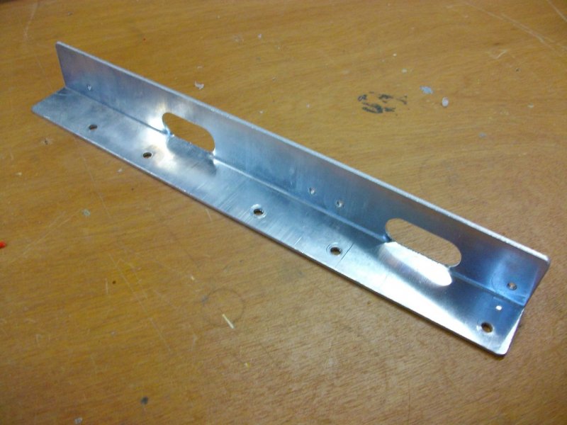
Hello here! I'm new to AutoCAD (mechanical) but I've seen some intro video's (getting started video's) from AutoCAD and are very exiting to get started! Since I'm total new with AutoCAD, it's pretty challenging I must say! Let me give an example... From the picture attached, I want to make a mechanical drawing. It's a standard bracket wich I intend to ' copy ' by a local supplier. But he needs a nice mechanical drawing, with messurements / dimensions etc. Is there somewhere a tutorial or getting started video on how to approach this? How do I draw the first lines, do I draw a line / box or can I betetr do it on a different way? If I start to draw, how do I deside or let AutoCAD know wich view (front / side / etc.) I'm drawing? And because the bracket is allready bend, how do I meassure the correct dimensions in account for the thickness of the aluminium? Do I measure the inside of the bracket or the outside, or do I need to extract the thickness (2mm) from a certain meassurement? I have done some electrical CAD drawings with Cadsoft Eagle (for designing electronic designs and Printed Circuit Boards) but this is a whole different story... Hope someone is willing to help me with this one! Thanks for the time!
- 102 replies
-
- mechanical
- help wanted
-
(and 2 more)
Tagged with:
-
I am currently trying to make a bracelet with text engraved in the outside of it with autocad, and my current problem is that I have to make the text 3D before I can subtract it from the bracelet. I am using autocad for mac, which means I dont have the express tools, most notably textexp. I am fairly sure that, without other programs, making 3d text with autocad for mac is impossible. I have tried making text in adobe illustrator, outlining it, and exporting it to autocad, but when I explode it (with the default explode command) and extrude the text, it looks like this: As you can see, very few of the letters get properly extruded, and some arent even effected at all. I've tested other fonts, and they all have the same problem, albeit with some differences in exactly which letters are changed. Except papyrus, in which none of the text gets extruded If anyone knows how to make outlined text from illustrator extrude properly, be my guest! The same goes if you have a different way to make 3D text. All help will be appreciated.
- 2 replies
-
- mac
- help wanted
-
(and 2 more)
Tagged with:


