Search the Community
Showing results for tags 'grips'.
-
Inserting Dynamic Blocks along the points of Polyline using LISP
sanetmunde posted a topic in AutoLISP, Visual LISP & DCL
Hi, I want a LISP routine which can insert blocks along the polyline. I have two dynamic blocks. They are 'Straight Duct' and 'Elbow90'. Consider I draw a polyline with three XY coordinates i.e. (1,1) , (1,2) and (2,2) and insert rectangular block with desired 'Width'. Here are list of things I want from LISP program: 1. I want 'Straight Duct' to be inserted at mid-points of '(1,1) & (1,2)' and '(1,2) & (2,2)'. 2. Also, those inserted blocks should be rotated with an angle made by those points with horizontal so that 'Straight Duct' remains along the line. Example, Angle made by line joining points '(1,1) & (1,2)' with horizontal is 90 Deg. Hence, Dynamic Block should be rotated by 90 degree about midpoint. 3. Move the grip of 'Straight Duct' (which facing to open end of polyline) to the open end of polyline. Move other grip of 'Straight Duct' to the length of (150+ Width/2) mm less than the intersection point. 4. Insert 'Elbow90' at the point with polar angle 45 Degree to point of intersection and polar radius (150 + Width/2) mm. Also, the grip of elbow should be moved so that width of 'Elbow90' should be as same as that of 'Straight Duct'. Pls refer the attached file for understanding the problem. Can anyone help me out? HVAC Dynamic Blocks 24.04.2018.dwg- 8 replies
-
- autolisp
- block attribute
-
(and 2 more)
Tagged with:
-
Hello, I have a file with a block made of some simple lines and arcs. When I view it on screen, the lines and arcs do not meet at common endpoints. When I edit with the grips, they grip the points correctly but the grips do not match the 'visual' endpoints. Additionally, everything plots perfectly. I have set viewres to the max value with no results. I am ending up with 'x's at the corners. What settings am I overlooking? Thanks, Phil
-
Can a lisp programmer review my code to find out what's not working? This code will restore an attribute's grip when used with BricsCAD, Draftsight Professional, ZWCAD 2014, 2015, 2017.... But doesn't work in AutoCAD which is what I use most of the time. The grip apparently is controlled by LOCKED option when creating the attribute tag. ; ULMA - Work properly in ZWCAD, Draftsight, and BricsCAD...but not AutoCAD ; UnLockMyAttribute ; Steve Remenda ; July 30/2014 ; July 5/2016 Tried again to get grips turned back on. no success. ; DXF code 280 lock position flag within the block reference should be 0 (defun c:ulma ( / cmd enam edat1) (setq cmd (getvar "cmdecho")) (setvar "cmdecho" 1) (setq enam (car (nentsel "\nSelect Select attribute turn on grip: "))) (setq myinsert (cdr (assoc 330 (entget enam)))) ;get the block (setq my280 (cdr (assoc 280 (entget enam)))) ;get current 280 cons value (if (= my280 0) ;if the attribute is locked (progn (setq myval 1); 1 to show grip (setq edat1 (subst (cons 280 myval); ; Change the DXF code pair (assoc 280 (entget enam)) (entget enam) );subst );setq - this does display the list and cons 280 does show a 1 (entmod edat1) ; but this returns nil. Should it? (entupd enam) ; this should update the attribute (entupd myinsert) ; this should update the block ); progn then when lock is visible (progn ; Else attribute is something else (initget 1 "Yes No") (setq x (getkword "\nThis attribute grip is already on. Do you want to turn it off? (Yes or No) ")) (if (= x "Yes") ; if user wants to apply italics (progn (setq myval 0); 0 For No grip (setq edat1 (subst (cons 280 myval) ; Change the DXF code pair (assoc 280 (entget enam)) (entget enam) ); subst ); setq (entmod edat1) (entupd enam) ); progn to make attribute visible ); if Yes response );progn Else attribute is something else ); if an attribute is selected. (command "REGEN") (setvar "cmdecho" cmd) (princ) ) ;ulma - UnLock My Attribute
- 1 reply
-
- locked attribute
- grips
-
(and 2 more)
Tagged with:
-
I have been working in AutoCAD for many years and this one I have never figured out. I want 2 grips to show up with one of my blocks, how do I do that. I have a lot of blocks that I work with and a lot of them have a ton of grips that I do not want to have to deal with so I have turned grips off in blocks yet this causes another problem. I have one block that I need more then one grip to be able to use it. is it possible to have multiple grips show up in one block yet not in others?
-
Hello, I am trying to get two lines to rotate about two opposing circles whilst being able to stretch and also being joined together at opposite ends to the circles , so they can be controlled with one grip at the apex. I have been able to have the one set to work as i wish, but I can not get it to work for both at he same time. I can move the two lines as I wish that are not in a block, but can not get the lines to rotate about a circle, only at the start point. Any ideas or solutions would be greatly appreciated I feel like I have tried everything. Thanks. a.dwg
- 3 replies
-
- grips
- dynamic stretch
-
(and 2 more)
Tagged with:
-
When I select a solid I can never know where the grips will appear. I personally would like to have grips on the edges (vertex?) points and other geometrically interesting points (centers of arcs, circles..). Is there a way to get it
-
Anyone know how to get rid of this garbage in the attached picture? I remember when it was only Ustation that caused this grief. I guess autodesk decided to catch up
-
Multiple Hatch Grip Removal
nsc23 posted a topic in AutoCAD 2D Drafting, Object Properties & Interface
Hi Guys, Trying to remove multiple hatch grips. My problem is as simple as that! Since 2011 brought in the pop-up option, single grips can be removed with this method. But when I want to delete a larger number of grips at once, I can't achieve the required result. Process is as follows: 1. Select Hatch itself 2. Holding SHIFT, select multiple grips (which turn from blue to red) 3. Then 1 left click on a grip, and scrolling through the options using CTRL key until I arrive at 'REMOVE'. Then another left click and nothing happens! Any assistance would help with avoidance of head being done in! Cheers, Clarky. -
I have been trying to figure this out for the past couple of days with no luck. In the editor I am able to select a polar grip from a dynamic block and place it where needed, it updates stretch and angle for custom properties on the dynamic block. I am looking for a way to do the equivalent in C#. This is what I have tried so far public void MoveGrip(Point3d gripPoint, Vector3d offset) { Document doc = Autodesk.AutoCAD.ApplicationServices.Application.DocumentManager.MdiActiveDocument; Database db = doc.Database; Transaction tr = db.TransactionManager.StartTransaction(); using (tr) { BlockReference br = null; Entity ent = (Entity)tr.GetObject(_oBlockRefId, OpenMode.ForWrite); br = ent as BlockReference; if(br != null) { GripDataCollection grips = new GripDataCollection(); GripDataCollection updateGrip = new GripDataCollection(); double curViewUnitSize = 0; int gripSize = 0; Vector3d curViewDir = doc.Editor.GetCurrentView().ViewDirection; GetGripPointsFlags bitFlags = GetGripPointsFlags.GripPointsOnly; br.GetGripPoints(grips, curViewUnitSize, gripSize, curViewDir, bitFlags); foreach (GripData grip in grips) { if (grip.GripPoint == gripPoint) { updateGrip.Add(grip); } } br.MoveGripPointsAt(updateGrip, offset, MoveGripPointsFlags.Polar); } } } It does collect points, and match with the point passed in(as I know know other way to specify what point I want to move). But when it tries to execute MoveGripPoibtsAt nothing is changed, and no exceptions are thrown that I am aware of. I have also spent a couple of days trying to find documentation for this, with no luck. Where the hell is the api documentation for autocad 2013? I keep finding stuff for civil and others, but nothing for autocad. This is immensely frustrating.
-
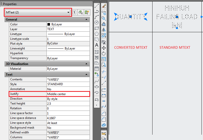
Hi, I've noticed in AutoCAD 2012 that the MTEXT grips have changed, for example, MTEXT justified to 'middle centre' displays just 3 grips, one centrally for moving and 2 'arrow' style grips for stretching. In previous versions of CAD which I used, the MTEXT would have 5 grips, the additional 2 giving more versatility when placing text. However, when using the TXT2MTXT command the resulting MTEXT will display 5 grips (see image). What I would like to know is if it's possible, perhaps with a system variable, for normal MTEXT to display 5 grips as standard as mentioned above? I've searched the help files and the forum but have found nothing... Thanks
-
Hi, Hi, I recently upgraded from Autocad 2011 to Autocad 2012. When editing hatch in 2011 I used to be able to single click the hatch pattern, and then use one of the many grips to edit it, but now, when single clicking the hatch pattern in Autocad 2012, only one grip appears in the centre, in the form of a blue dot? How do I set my Autocad 2013 to behave as it did in Autocad 2011? Thanks in advance
-
So I've been toying around with AutoCAD Electrical 2013 for a couple weeks now. I've been trying to figure out a way to adapt it to create P&ID drawings. There seems to be a lot more setup work involved but for now I've been mainly trying to convert my custom P&ID symbols to ACADE symbols using Symbol Builder. I thought I had the basics figured out until I inserted the first said blocks from the Icon Menu dialog box. The original block turned component symbol now shows all of the wire connection attribute grips when selected instead of just the insertion point grip. I have no idea what went wrong. I should note that these blocks also have dynamic attributes like flip, scale, and visibility. I've looked around on the web, through the ACAD help, and did a couple searches here to find a similar problem to no avail. Anyone have any insight into this issue? These kinds of issues make me wish the "higher up's" had listened when I said we need to switch to P&ID but that's a whole other issue I won't get into here...
- 2 replies
-
- symbol builder
- grips
-
(and 2 more)
Tagged with:
-
This is probably another one of those "quirks." I report it in the hope that, late in the 22nd century or so, someone will get around to fixing it. When I use Quick Select to find the objects on a particular layer, they are normally highlighted, and I can see the grips. Every so often that doesn't happen. I can still see the properties of the selection set, so the command has worked. If I select one of those objects, the rest are magically highlighted. Sometimes I select objects by layer simply to find out how many are there and where they are, so this particular quirk is frustrating. What makes it happen? If I knew, it would be a bug, not a quirk. At a guess, it happens after I've done several Quick Selects in a row.
-
Block malfunction(s) & geometry detaching from grips afterwards
ARainey posted a topic in AutoCAD Bugs, Error Messages & Quirks
Strange problem here in AutoCAD 2009: Inserting a block mainly made up of attributes (some text, no geometry) picking a point on screen (free point: no snap, no coordinate entry) attdia is set to 0 when entering through default values at the command line the block on screen seems to be offset from my pick point (offset seems to be relative to 0,0 also) if I go all the way through the block, no problems except it is kind of annoying to have the block not show up in the right place while going through the atts the first time bigger problem is if I escape during the att editing and then draw any geometry that same offset referred to earlier is apparent when drawing and my grips are now detached from my geometry!!!! a regen will fix the new geometry and line it back up with the grips but it shifts any existing geometry too!!! Pretty hard to explain actually, Been looking for a solution for a couple days now, best I can tell it is some kind of coordinate problem with my blocks? UCS, ECS? Sysvar? I've run an audit on my template and the block with no errors, tried making a fresh block with same characteristics, same problem. Help please! Thank you!- 2 replies
-
- coordinates
- blocks
-
(and 2 more)
Tagged with:
-

Edit multiple grip points at the same time by using HOT grips
Oppie posted a topic in AutoCAD 3D Modelling & Rendering
Hi, here is a short tutorial on how to edit multiple grip points at the same time using Hot grips: http://www.youtube.com/watch?v=sUvX3uB6mqo enjoy :wink: -
Can't Stretch Dimension with Grips
Cadesignpro posted a topic in AutoCAD 2D Drafting, Object Properties & Interface
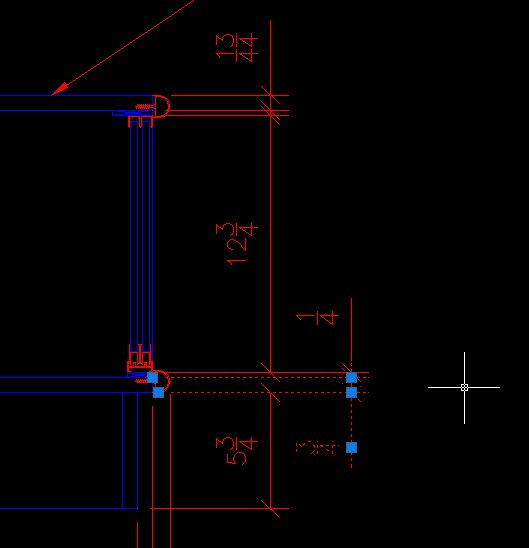
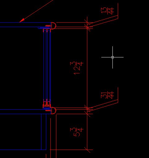
I am recently having trouble with a few dimensions not wanting to adjust there position via grabbing the grip at the arrow/extension line intersection. It seems to only happen when the dimensions are:1. created using "continue dimension" 2. Then updating the dimension (to get rid of the angled text leader on a small dimension) 3. Then moving the text, with a grip, to the opposite side of the dimension. After that I can't move the dimension location via grips anymore. If I create the exact same dimensions using "Linear Dimension" I have no problems.-
- dimensions
- autocad
-
(and 1 more)
Tagged with:

