Search the Community
Showing results for tags 'flexible duct'.
Found 1 result
-
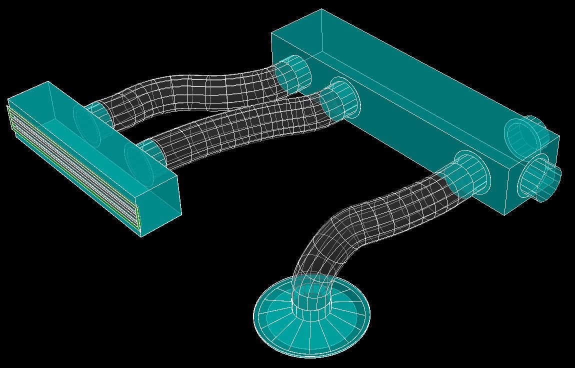
Hi guys, I'm new to this forum and new to programming with lisp - please be kind.... The code I am writing will draw a 3dPolyline from a specific point to another point (usually with a lower z coordinate), the polyline will then be converted to a spline, a circle will be drawn at the start of the 3dPolyline and extruded along the spline to form a "curved tube". The intention is to use this as a flexible duct from a "spigot" on an A/C duct to a ceiling diffuser. The 3dPoly has to be perpendicular to the start point and end point for obvious reasons - see intentional misalignment picture. Below a portion of the unfinished code to select the start point, select the endpoint, then it must start drawing the 3dpoly from the start point, get a variable number of user input points (in order to define the initial direction and plane) and general path of the flexible duct. The end point of the 3dpoly is already defined with the initial selection of the "Endpoint on Diffuser" although the 2nd last point has to be mathematically determined considering the plane must be perpendicular to the end point. So - after selecting say 3 or 4 user defined points along the path, I want to be able to press enter, and the code must then calculate the 2nd last point and continue drawing the 3dpoly from the last picked point, to the calculated 2nd last point and then to the endpoint. Generally one has to be mindful that the curve of the tube cannot have a "sharp bend" - smooth curves are ideal for the airflow. The diameter of the tube will also change depending on the specific size requirements. Attached a small drawing and picture to show the intent. The crux of my problem: I cannot figure out how to start the 3dpoly command, make it pick the start of the line, then hand over to the user to continue picking 4 or 5 points, press enter, and then continue drawing the 3dpoly with calculated numbers? Would really appreciate some guidance. Maybe use of cmdactive? I really do not know enough to figure this one out. (defun C:Flex250 () (command "_.layer" "_thaw" "HVAC Flex" "_make" "HVAC Flex" "") (setq Prev_OM (getvar "OSMODE")) (setvar "OSMODE" 8) (setq StartPoint (getpoint "\nEnter Start Point on Duct Spigot : ")) (setq EndPoint (getpoint "\nEnter End Point on Diffuser : ")) (setq Z0 (caddr EndPoint)) (setq Z1 (+ (caddr EndPoint) 50)) (setq Z2 (+ (caddr EndPoint) 150)) (setq pt0 EndPoint) (setq pt1 (list (car EndPoint) (cadr EndPoint) Z1)) (setq pt2 (list (car EndPoint) (cadr EndPoint) Z2)) (SetVar "Elevation" (princ (caddr StartPoint))) (command ".3DPoly" (princ Startpoint) (getpoint "\nNext point : ") pt2 pt1 pt0) ) Then a last question - is there a way to ensure the spline's start and finish points are 100% perpendicular to the planes they connect to? Thank you in advance for your input. Test.dwg


.jpg.7ebd8746138284fcdebcc66a1bacb533.jpg)