Jump to content

Search the Community

Showing results for tags 'distance'.

  • Search By Tags

    Type tags separated by commas.
  • Search By Author

Content Type


Forums

  • CADTutor
    • News, Announcements & FAQ
    • Feedback
  • AutoCAD
    • AutoCAD Beginners' Area
    • AutoCAD 2D Drafting, Object Properties & Interface
    • AutoCAD Drawing Management & Output
    • AutoCAD 3D Modelling & Rendering
    • AutoCAD Vertical Products
    • AutoCAD LT
    • CAD Management
    • AutoCAD Bugs, Error Messages & Quirks
    • AutoCAD General
    • AutoCAD Blogs
  • AutoCAD Customization
    • The CUI, Hatches, Linetypes, Scripts & Macros
    • AutoLISP, Visual LISP & DCL
    • .NET, ObjectARX & VBA
    • Application Beta Testing
    • Application Archive
  • Other Autodesk Products
    • Autodesk 3ds Max
    • Autodesk Revit
    • Autodesk Inventor
    • Autodesk Software General
  • Other CAD Products
    • BricsCAD
    • SketchUp
    • Rhino
    • SolidWorks
    • MicroStation
    • Design Software
    • Catch All
  • Resources
    • Tutorials & Tips'n'Tricks
    • AutoCAD Museum
    • Blocks, Images, Models & Materials
    • Useful Links
  • Community
    • Introduce Yourself
    • Showcase
    • Work In Progress
    • Jobs & Training
    • Chat
    • Competitions

Categories

  • Programs and Scripts
  • 2D AutoCAD Blocks
  • 3D AutoCAD Blocks
  • Images
    • Backgrounds

Find results in...

Find results that contain...


Date Created

  • Start

    End


Last Updated

  • Start

    End


Filter by number of...

  1. Hello everyone. I created this lisp with the help of chatgpt I need your help to complete this. I've attached a CAD file for your reference as what I'm looking for. I have some idea in my mind but I don't know how to execute that. 1. required distance between last and next 1st point (to creat red line- refer CAD file) 2. calculate the distance from next 1st point. (to extend the cyan line- refer CAD file) If you modify in my lisp, it will be really helpful me to learning. 2023-04-30 Test.lsp 2023-04-30.dwg
  2. I Want Required lisp Export Data of 3DPolyLine To CSV "Chainage" And "Elevation" This lisp Proposed use for Cross Section.
  3. lets say i have two circles apart 1000mm now i need to adjust the distance to 700mm what should i do without deleting any one object?
  4. I have an attached dwg here. I want a list routine that will extract the lot's (from mother lot to sublots) bearings and distances just like in the dwg. The tables will be inserted one by one like mother lot first, then sublot-a then sublot-b and so on. (also the bearings and distances from the reference point to the different corner 1) Thank you so much. I really need this routine to finish my study. I've read tutorials and blogs, but still can't get it right. Hope that someone can help me. thanks.
  5. Hi guys, Long time ago ,I have written this lisp routine, This routine inputs a reference points coordinates, elevation and distance values from screen. It calculates several new points elevation and distance values and writes their elevation and distance values on screen. Can anyone help me compiling this routine in to vba code (defun C:x() ;We define the reference point (command "osnap" "int") (setq prop (getpoint "Define the reference point:")) (setq propx (car prop)) (setq propy (cadr prop)) (setq n 100) ;We define the reference point elevation (setq ropkot1 (entget (setq ropkot (car (entsel "\n Define the reference point elevation:"))))) (setq ropkot2 (cdr (assoc 1 ropkot1))) (setq ropkoti (atof ropkot2)) ;We define the reference point distance (setq ropmes1 (entget (setq ropmes (car (entsel "\n Define the reference point distance:"))))) (setq ropmes2 (cdr (assoc 1 ropmes1))) (setq ropmesi (atof ropmes2)) ;We pick up the new point (repeat n (command "osnap" "end") (setq p1 (getpoint "Define new point:")) (setq p1x (car p1)) (setq p1y (cadr p1)) (command "osnap" "none") (command "color" "white") (command "line" (list p1x p1y) (list (+ p1x 1.575) (+ p1y 2.1)) "") (command "line" (list (+ p1x 1.575) (+ p1y 2.1)) (list (- p1x 1.575) (+ p1y 2.1)) "") (command "line" (list (- p1x 1.575) (+ p1y 2.1)) (list p1x p1y) "") (setq m1 (- p1x propx)) (if ( (setq kot (+ ropkoti (/ (- p1y propy ) 10))) (command "text" (list (- p1x 3.0) (+ p1y 2.5)) 1.8 0 (rtos kot 2 2)) (command "text" (list (+ p1x 0.75) (- p1y 7)) 1.8 90 (rtos (abs mesafe) 2 2)) )
  6. Hello, I have this Lisp MD (Closest Distance Between Two Objects).lsp that can show me what is the shortest distance between two objects. If you type MD it shows the distance value and if you type MDL, it draws a line between them on the closest point distance. It can be useful for you if you need. But I need the right opposite of it. I need the Longest Distance between two objects. I need the number and the line of it. Can someone help me?
  7. I have a polyline, which is made of lines and arcs. One or more arc could have radius smaller than offset distance (offset direction to inside of arc). Basically autacad says "Cannot offset that object". In this case i must xplode polyline and offset other part of polyline without the problematic arc, chamfer them and make it polline again. Is there any workaround? Many times I have to draw polylines and offset them and it drives my crazy
  8. toxicsquall

    Deleting Points

    Good afternoon, I need to delete all points between 0 cm and 15 cm spacing. If I can use an object as a base or a layer it will be even better. With OVERKILL command it deletes randomly objects that only are overlapping. Is there any lisp that can make this?
  9. jkoll66

    direct distance entry

    I have a colleague using AutoCAD 2016. When he tries to draw a line using direct distance entry it sometimes works and sometimes does not. It is very erratic. It seems to not work more often when he is drawing the line off of another object. Anyone know what's going on here? Thanks.
  10. Hi, hello everyone. i am new to autolisp. i need a routine that can calculate distance between two points and write it down to active cell of active workbook. (wherever selected in excel). Is it possible? will be very helpful to me. Thanks
  11. Hi Everyone, Just wondering if anyone knows of a good lsp routine for doing the following, or if anyone knows how to do this with built in capabilities in AutoCAD 2015. Basically I want to annotate angles and distance for survey drafting so I can produce plans that look like this plan that I've attached. I have a routine that will give me the distance and bearing and place it parallel to a line but now I need to be able to do the same with the angle (in degrees/minutes/seconds) and distance (in meters) so that the angle appears as it does in the attached sample. Any help would be most appreciated! Thanks!
  12. Just like usual ran an existing and proposed ground profile for a standard road. In my base plan the SSD is 172.85' When I XREF the profile into another drawing the sight distance has changed to 2,490.22. I checked to make sure the scales are the same, they are. Any other ideas? I am really stumped on this one. As always, thanks for any and all help. Regards, Miller
  13. When entering distances, I would type in for instance, 2'6 and CAD interprets that as being 2 feet and 6 inches by default. My question is, is there a way to set it so I can so I can enter 2-6 and get 2 feet 6 inches instead of using the ' tick mark sign? it's a lot easier and faster to do it with the dash since I am drawing a ton of drawings and the dash is included on the right number pad on the keyboard?
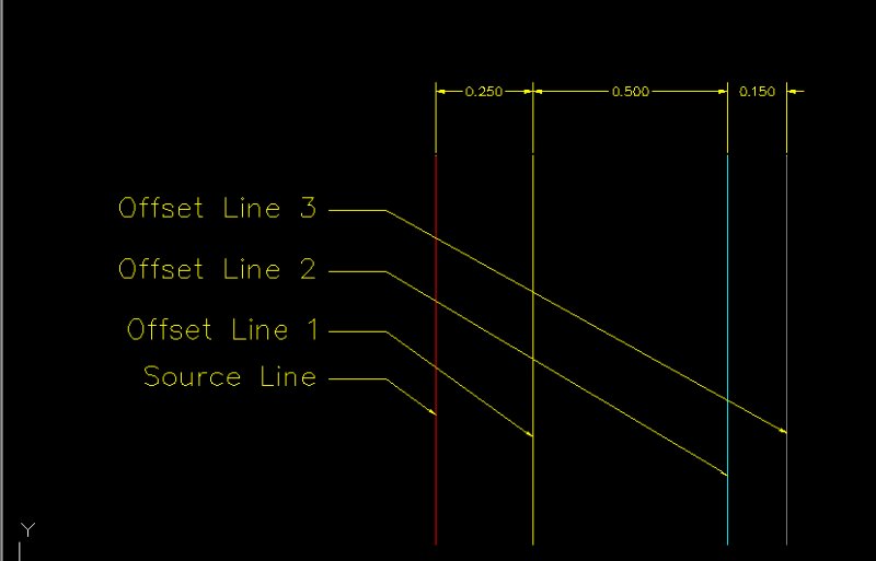
  14. Hello, I have a Drawing in which I need to draw thousands of parallel lines (offset) on different distances. Is there anyway or Lisp Routine which can help me to Draw all the offsets at once for each line. see the screenshot below for reference. Thank You, Regards, Sidhu
  15. Hello, If you are looking at plan view, I have a bunch of points surveyed for blastholes: x x x x x x x x x x x x x x x x These points all vary in height. I have a surface created under hole collars representing the chemical contact between two different rock units. I'm trying to project a line from the collar of the blast hole, vertically down, to intersect with the surface and determine that length so I can inform the drillers what depth the holes need to be drilled to. Currently, here's my workflow to get the required depths: Survey the blast hole locations prior to drilling. Come back to the office, import my points from the survey to CAD. Determine the extents of the blast. Extend the existing geologic model to determine the hypothetical depths. The drillers then drill sample holes to determine the depth of the surface and the surface is updated within two days. I then need to go back out to the blast holes and use my survey equipment to stakeout the DTM. I then go back around to the holes and record on scratch paper the depths to the DTM. I then come back to the office and annotate the drawing with the required depths. I then finally plot the drill instructions for the blasthole drills. I appreciate any and all help!!
  16. Hello guys, well i have a homework for the exams and i have no time, so i need your help. The question is, how i can measure the exact length of an arc (or a polyline) ? See the pic.
  17. Is there any way to find out the Maximum vertical distance between two polylines?
  18. I'm using cad 2013 and my boss needs something that appears smaller as it fades into the distance. it has occurred to me that I've always looked past the fact that autocad makes everything the same size (i.e. any circle drawn at 90mm will look the same in front view no matter how far you space them in top view). So the program doesn't give the natural "fading into the distance" effect. is there a way to make it look more realistic using a view or rendering or something that I am unaware of?
  19. Hi, I need to calculate distance between two points along a polyline. These points may exist on different segments of the same polyline. Maybe there is a function, I couldn't find it. I'd be very grateful for your help.
  20. I have 2 lisp routines help draw bearing line and label them but i would have to do 2 command seperately so i am seeking someone help me combine them together. command 1 is to draw the bearing... ;Tip1741: BD.LSP Bearing/Distance lines (c)2001, Joon Hong $50 Bonus Winner (defun C:BD () (setvar "cmdecho" 0) (initget 1) (setq PT (getpoint "\nPick a starting point: ")) (initget 1 "NE NW SE SW") (setq BR (getkword "\nPick bearing (NE/NW/SE/SW): ")) (setq OPT (strcase BR)) (initget 1) (setq LEN (getreal "\nType the length: ")) (setq DEG (getstring "\nType the degree: ") minx (getstring "\nType the minute: ") SEC (getstring "\nType the second: ")) (if (= DEG "") (setq DEG "0")) (if (= minx "") (setq minx "0")) (if (= SEC "") (setq SEC "0")) (cond ((= "SW" OPT) (setvar "angbase" (cvunit 270 "degree" "radian")) (setvar "angdir" 1)) ((= "SE" OPT) (setvar "angbase" (cvunit 270 "degree" "radian")) (setvar "angdir" 0)) ((= "NW" OPT) (setvar "angbase" (cvunit 90 "degree" "radian")) (setvar "angdir" 0)) ((= "NE" OPT) (setvar "angbase" (cvunit 90 "degree" "radian")) (setvar "angdir" 1))) (command "line" PT (strcat "@" (rtos LEN) "<" DEG "d" minx "'" SEC "\"") "") (setvar "angbase" 0) (setvar "angdir" 0) (setvar "cmdecho" 1) (princ)) (princ "\nType 'BD' to draw lines with bearings") (princ) command 2 is to label the bearing line ; TIP752.LSP Distance and Bearing (c)1992, Roy Cook ;* distance and bearing label for lines (graphscr) (prompt "\nloading. . .") ;convert radians to degrees (defun rtd (R) (/ (* R 180.0) pi)) (defun C:brg2 () ;input for line notations (setq P1 (getpoint "\nfirst point: ")) (while (setq P2 (getpoint p1 "\nsecond point: ")) (setq T1 "text height: <default = " T2 ">: " T3 (getvar "textsize") );setq (terpri) (setq TH (getreal (strcat T1 (rtos T3 2 2) T2))) (if (= TH nil) (setq TH t3)) ;determine if bearings are true north, south, east, or west (defun nsew () (if (and (= (car P1) (car P2)) (< (cadr P1) (cadr P2))) (setq BNG "north") );if (if (and (< (car P1) (car P2)) (= (cadr P1) (cadr P2))) (setq BNG "east") );if (if (and (= (car P1) (car P2)) (> (cadr P1) (cadr P2))) (setq BNG "south") );if (if (and (> (car P1) (car P2)) (= (cadr P1) (cadr P2))) (setq BNG "west") );if );defun ;place text on line (setq AA (angle P1 P2) DS (distance P1 P2) P3 (polar P1 AA (/ DS 2.0)) AA1 (strcat (rtos (/ DS 12.0) 2 2) "'") );setq ;calculate bearing from coordinates and format for printing (defun bearing () (setq O (- (car P2) (car P1)) T (- (cadr P2) (cadr P1)) AZMTH (/ (* (atan (/ O T)) 180.0) pi) A (abs AZMTH) D (fix A) M (* 60 (- A D)) S (* 60 (- M (fix M))) M (fix M) );setq (if (= "60" (rtos s 2 0)) (setq M (+ 1 m))) (if (= "60" (rtos s 2 0)) (setq S 0)) (if (= "60" (rtos m 2 0)) (setq D (+ 1 d))) (if (= "60" (rtos m 2 0)) (setq M 0)) (if (< (cadr P2) (cadr P1)) (setq G "s") (setq G "n")) (if (< (car P1) (car P2)) (setq H "e") (setq H "w")) (setq BNG (strcat G "" (if (< D 10) (strcat "0" (rtos D 2 0)) (rtos D 2 0)) "%%d" (if (< M 10) (strcat "0" (rtos M 2 0)) (rtos M 2 0)) "'" (if (< S 10) (strcat "0" (rtos S 2 0)) (rtos S 2 0)) "''" "" H)) );setq ;bearing and distance on line (if (or (= 0 (- (car P1) (car P2))) (= 0 (- (cadr P1) (cadr P2)))) (nsew) (bearing)) (command "text" "m" (polar P3 (rem (+ AA (/ pi 2)) (* pi 2.0)) TH) TH (rtd AA) AA1) (if (or (> (car P1) (car P2)) (= (rtd AA) 270)) (command "rotate" "last" "" P3 180.0) );if (command "text" "m" (polar P3 (rem (+ AA (* pi 1.5)) (* pi 2.0)) TH) TH (rtd AA) BNG) (if (or (> (car P1) (car P2)) (= BNG "south")) (command "rotate" "last" "" P3 180.0) );if (command "line" P1 P2 "") (setq P1 P2) ) (princ);end program cleanly );defun thank you in advance
  21. If I click on an object, its nodes are highlighted. If I then click on a node (such as the end of a line), I can move that node. In this case, I drag it to the left and enter a distance (such as 1 foot), with ortho turned on. This should cause the point to move left exactly 1 foot. When I press "enter," the node moves up or down instead. It doesn't move left like it should have. I think it doesn't move *precisely* up or down, either, but goes a little to the left or right. It does, however, move the distance I typed in. Why won't the node go in the direction I want?
  22. Attached file shows a book cabinet. After manipulating the depth (32 cm) for many times, still I haven't got the ideal depth. Manipulating the distance is time consuming and I am looking for a smarter way to do it. Changing the depth is cumbersome for me, as I act in the traditional way. Let say if I want to change the depth of all shelves to 34, I choose 7 shelves from bottom, move all 2 cm down. In the next step I choose 6 shelves from bottom and move them 2 cm down and repeat until I reach the bottom. In order to draw them, first: I use rectangle not lines which has some shortfalls, second: I use array command to copy them down. This is not a smart way and I think there must be a better way. Although a LISP routine will solve it very easily, but I prefer a non-LISP solution. I would like to know how do you solve this matter? test-change length.dwg
  23. I have two locations marked by steel stakes on my land that are also shown on a CAD drawing. The CAD drawing is two dimensional; however, contours are shown. I have physically measured distances between these two known points and numerous other locations that I wish to plot on the CAD drawing. I could always print the CAD drawing to scale and plot the new points on the CAD printout by using the two known locations, a compass to draw arcs and locating the new points by where the arcs intersect. I am sure there is a much more efficient way to plot these new points within the CAD program itself. I have just started to use CAD; any help is appreciated.
  24. Hi everyone, is it possible to get a point on an "ellipse arc", in an specified distance to the start point of "ellipse arc"?
  25. Hi, I'm literaly just starting to use CAD so this might be a silly question, but how would I offset a line more than one distance in a command? Is there like a symbol you put between each distance like 2000;2250;2650 or something along those lines (no pun intended). Again sorry is this is a silly question. thanks
×
×
  • Create New...