Jump to content

Search the Community

Showing results for tags 'custom'.

  • Search By Tags

    Type tags separated by commas.
  • Search By Author

Content Type


Forums

  • CADTutor
    • News, Announcements & FAQ
    • Feedback
  • AutoCAD
    • AutoCAD Beginners' Area
    • AutoCAD 2D Drafting, Object Properties & Interface
    • AutoCAD Drawing Management & Output
    • AutoCAD 3D Modelling & Rendering
    • AutoCAD Vertical Products
    • AutoCAD LT
    • CAD Management
    • AutoCAD Bugs, Error Messages & Quirks
    • AutoCAD General
    • AutoCAD Blogs
  • AutoCAD Customization
    • The CUI, Hatches, Linetypes, Scripts & Macros
    • AutoLISP, Visual LISP & DCL
    • .NET, ObjectARX & VBA
    • Application Beta Testing
    • Application Archive
  • Other Autodesk Products
    • Autodesk 3ds Max
    • Autodesk Revit
    • Autodesk Inventor
    • Autodesk Software General
  • Other CAD Products
    • BricsCAD
    • SketchUp
    • Rhino
    • SolidWorks
    • MicroStation
    • Design Software
    • Catch All
  • Resources
    • Tutorials & Tips'n'Tricks
    • AutoCAD Museum
    • Blocks, Images, Models & Materials
    • Useful Links
  • Community
    • Introduce Yourself
    • Showcase
    • Work In Progress
    • Jobs & Training
    • Chat
    • Competitions

Categories

  • Programs and Scripts
  • 2D AutoCAD Blocks
  • 3D AutoCAD Blocks
  • Images
    • Backgrounds

Find results in...

Find results that contain...


Date Created

  • Start

    End


Last Updated

  • Start

    End


Filter by number of...

  1. Hello everyone, I have one issue with dimension properties where I want to know if something can be done. We work with meters as units, and we make a lot of details so we've found a format that suits our needs but it means a lot of manual overrides. Basically, the dimensions are to be displayed with meters as the units, and we have the two first decimals for the cm as is, but we write the next or next two decimals for the mm range as superscript, stacking the last two digits. Is there any way to have the precision set to .0000 and stack the last two digits as default as opossite to manually override each dimension? Thanks in advance!
  2. Hello people, is it possible to create custom paper size with autolisp, i found a lot of information how to select printer, paper, but i do not see anything for creating custom paper size.
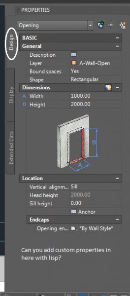
  3. Hi, I am running a version of autocad architecture with a plugin that adds some custom properties to AEC objects such as doors that can be viewed under the design tab of the property palette. I want to make a macro that changes these properties but I don't know how to access them via lisp. When I use the inspect window in the visual lisp viewer the custom properties don't come up and when I use the vla-dump-object function, the custom properties are not listed also. Does anyone have any idea if/how these properties are accessible? Also, can custom property fields be added via autolisp?
  4. Good Afternoon, I am working on an issue at my company and I hope I can get some help. I work at a metal panel company and I was hoping that I could insert a table that will update due to panel dimensions. What I would really like to see is a table that can give me Length and Width as well as the bends associated with the panel for fastening. What would be amazing is if I could get that table to give me the aforementioned information as well as being able to account for "corner panels", etc. since that is counted as one panel in this instance. Can this all be connected to a panel number? Please let me know if this is unclear. Thank you so much!
  5. I am trying to link the actual value of the length property of a polyline with a custom property I've created in a dynamic block. Basically, I would like to be able to link the property line length with a call out block that contains the line's length as "Count" property (Dbl). I've created a custom property to hold the numeric value (i believe this should be a Double value in order to sum values in table?) so I can then sum all lengths of similar call out blocks in a table. The reason I am using a custom property is so I can specify it as a Double value so the values will be able to sum up in the table. Using fields, I can link the poly line length to an attribute field but this becomes a string object which I can't add together in the table, as far as I understand anyway. What changes would I need to make to Lee Mac's awesome Lisp routines (huge fan of yours, Lee) to add this feature? I've attached the lisp file with the sub routines that seem useful for this task included, but I have quite a bit of trouble putting it all together. I've reverted all of Lee's subroutines back to the original code so none of my customization causes any errors. My end game is simple: Select the poly line(s), select the dynamic block to be associated with said line(s), and then populate the custom "Count" property with the length of the selected poly line(s) as a Double value. This will allow me to summarize the total length using data extraction and a table. Any help with this would be greatly appreciated, and please include the why & how if you have the time so I can learn and share with others You guys are the best, thanks in advance! Count.lsp PROP_CO_1.dwg
  6. Hello, I am attempting to draw a custom stairs using the spline command, but I've never used the spline command and my lines are not smooth. Does anyone have a tutorial that I can watch to make sure my line comes out nice and smooth ro a trick up their sleeve. Thanks William
  7. I have written a little small command to run revision cloud on last object (i.e. rectangle, pline, circle...etc) and it works fine but I was trying to figure out a way to run that custom command after drawing my rectangle or pline. Instead of having to type the shortcut immediately after, every time. Here is custom rev cloud command I am referring to, this one works flawlessly when run as a standalone after I finish drawing said object that it will be used on but I would like to combine.. see below: (DEFUN C:RCL () (COMMAND "REVCLOUD" "O" "L" "") (COMMAND "-INSERT" "REV-TRI" PAUSE "" "" "") (COMMAND "EXPLODE" "L" "") (COMMAND "DDEDIT" "L" "") (PRINC)) Here is rectangle command with the attempt to run custom afterwards. It works but looks buggy and most likely written wrong. (take it easy ive been learning): (DEFUN C:RECL () (COMMAND "RECTANGLE" PAUSE PAUSE) (C:RCL) (PRINC)) Here is my attempt at the pline one but I dont even know where to start so it allows user unlimited points then hitting "c" for close afterwards AND THEN running the custom command: (DEFUN C:PLR () (command "_.PLINE") (coMmand pause) (C:RCL) (PRINC))
  8. I'm working in millimeters and whenever I use the AREA command I end up with a large number. I want to know if you can customize the AREA command somehow to show meters squared automatically.
  9. Hi I've tried to find som step by step guide on how to create content like a Metal Profiled Sheet Deck. I want to make a detail component showing a composite of 16mm Leweis Dovetailed Sheeting with cast concrete and possibly Pex tubes for floor heating. I want to make the details insertable as sections in both directions and in plan view. I want to make the thickness of the concrete ajustable (also after insertion). I want to make the section length to be ajustable, so the lenght of sections can be modyfied. I want to make the component with hatch for concrete associative to the metal profile and concrete. I have made a dynamic block, but it has some problems among others with the profile ends in sections. I have made a linetype with the dovetailet profile, but it is affected by the annotation scale. Im not looking for solutions in 3D. Please help
  10. Hello, I spend a lot of time to find idea how to set paper custom size. i.e. I have drawing, and I want to print it. Drawing in layout has 920mm x 875mm. My plotter has defined this size but I want to plot to PDF by DWGtoPDF.pc3. How to add new custom size of paper (920mm x 875 mm or other...) so that after this I could set in ThisDrawing.ActiveLayout.CanonicalMediaName=myCustomSizeName . I have a lot of drawing and almost every has another size so adding in autocad manually once is not enough. Do you have any ideas?
  11. calafragilistic

    "Arc"-like Leader

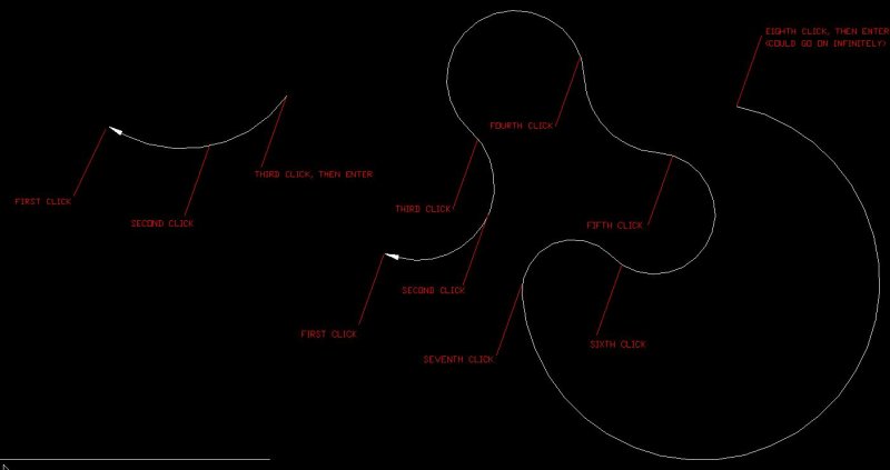
    When I used to use R14, I had a customized leader command where the first click was the endpoint of a leader (as usual), the second click was like the midpoint of an arc, and the third click was the other endpoint of an arc. You could continuously keep clicking and producing more arcs connected to the leader block, but typically I would just end the leader there, and it would not end with a text attached to it. Since I upgraded to AutoCAD 2010, the LISP function that I used for that did not transfer over, but I would like to have that again, as the spline leaders that are standard in 2010 look terrible compared to what I used to have, and are nowhere near as versatile. Is there a place I can find a LSP command to do the same thing, or will I have to rewrite the new command again? Here are some examples of how the finished 'CLeader' looked:
  12. I'm looking for some help writing macros and making custom commands with AutoCAD LT 2016. I remember learning this in college and have since tried following guides on the internet and it seems a little more complex than I remember. I often use "-dimstyle, enter, enter, enter, select dimension" to make the selected dimension the current style (I switch between drawings often when noting a design package). I've gone through the CUI a few times with little success trying to get a macro to do this. Can someone let me know how to make a custom command or an icon to do this for me. Thank you!
  13. rileybreed

    Section Arrows

    I'm running Inventor 2015. I am wondering if there is a way to make custom section arrows instead of what is defaulted on the system? I have clients that have their own standards for drawings and have a custom section arrow and titles. Is there a way to make a custom one without just making a sketch or plain symbol not related to the section? I'm trying to keep the drawing intelligent...
  14. Automonkey

    Custom Poly line/Path Array

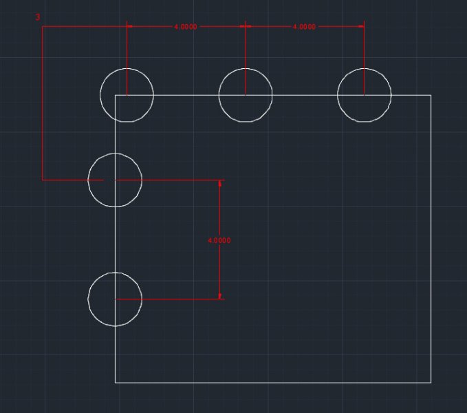
    Hello Y'all, In short I am looking to find a way to make a path array with changing lengths in between whenever there is a kink or turn in the polyline. For example, if I had a simple square "[]" and wanted to array circles around it, how would I make an array in which everytime there is a turn the path lengths between the circles before and after the turns have a different specific distance from the global array distance? Refer to the photo I am well aware of being able to manually adjust arrays by Ctrl clicking but in essence I am looking for a more automated way and if possible a more rule based array. Any ideas? Thank you!
  15. Hey all, I am working to set up a lisp where the user can edit the titleblock, update revblocks. We have templates that use the "custom" tab on the drawing properties box that tie into the titleblocks we use. I'm looking to just make it so the user can use this lisp instead of opening the dwgprops box everytime. Here's what the dwgprops box looks like: This is what I got so far: (defun c:TB () (if (setq Opt (getint "\nDo you want to: 1- Update Titleblock 2- Update RevBlock 3- Update Drawing Titles: " ) );;user input for variable "opt" (progn (cond ((= opt 1);;if user picks to update titleblock (setq titletop (getstring "\nWhat is title top? ")) (setq titlemiddle (getstring "\nWhat is title middle? ")) (setq titlebottom (getstring "\nWhat is title bottom? ")) ) ((= opt 2);;if user picks to update revblock (setq row (getint "\nWhich revision row do you wish to edit? ") ) (progn (cond ((= row 1) (setq 1rowrev (getstring "\n1st row rev: ")) (setq 1rowyy (getstring "\n1st row year: ")) (setq 1rowmm (getstring "\n1st row month: ")) (setq 1rowdd (getstring "\n1st row day: ")) (setq 1rdesc (getstring T "\n1st row description: ")) (setq 1rowby (getstring "\n1st row by: ")) (setq 1rowchk (getstring "\n1st row chk: ")) (setq 1roweng (getstring "\n1st row eng: ")) (setq 1rowapp (getstring "\n1st row app: ")) ) ((= row 2) (setq 2rowrev (getstring "\n2nd row rev: ")) (setq 2rowyy (getstring "\n2nd row year: ")) (setq 2rowmm (getstring "\n2nd row month: ")) (setq 2rowdd (getstring "\n2nd row day: ")) (setq 2rdesc (getstring T "\n2nd row description: ")) (setq 2rowby (getstring "\n2nd row by: ")) (setq 2rowchk (getstring "\n2nd row chk: ")) (setq 2roweng (getstring "\n2nd row eng: ")) (setq 2rowapp (getstring "\n2nd row app: ")) ) ((= row 3) (setq 3rowrev (getstring "\n3rd row rev: ")) (setq 3rowyy (getstring "\n3rd row year: ")) (setq 3rowmm (getstring "\n3rd row month: ")) (setq 3rowdd (getstring "\n3rd row day: ")) (setq 3rdesc (getstring T "\n3rd row description: ")) (setq 3rowby (getstring "\n3rd row by: ")) (setq 3rowchk (getstring "\n3rd row chk: ")) (setq 3roweng (getstring "\n3rd row eng: ")) (setq 3rowapp (getstring "\n3rd row app: ")) ) ((= row 4) (setq 4rowrev (getstring "\n4th row rev: ")) (setq 4rowyy (getstring "\n4th row year: ")) (setq 4rowmm (getstring "\n4th row month: ")) (setq 4rowdd (getstring "\n4th row day: ")) (setq 4rdesc (getstring T "\n4th row description: ")) (setq 4rowby (getstring "\n4th row by: ")) (setq 4rowchk (getstring "\n4th row chk: ")) (setq 4roweng (getstring "\n4th row eng: ")) (setq 4rowapp (getstring "\n4th row app: ")) ) );;end cond );; end progn );;end opt 2 ((= opt 3);;if user picks to update drawing titles, still figuring this section out ) );;end cond );;end 1st progn );;end 1st if );;end defun What I'm having the hardest time figuring out is how to take the user inputted values and place them into the correct custom drawing properties, this only applies to the revbock updates. I also don't know how to take the title user inputs and put them into the correct drawing property location (although I figure they are closely related) I did find this list which may prove to be helpful in the hunt, but I don't know how to translate it into something useful... Thanks for any and all help!
  16. Hello All I have a simple iLogic Rule which converts the Mass (kg) iProperty into a Custom iProperty measured in tonnes, to 2 decimal places. [color=#800080][b]iProperties[/b][/color][color=#000000].[/color][color=#800080][b]Value[/b][/color][color=#000000][b]([/b][/color][color=#008080]"[/color][color=#008080]Custom[/color][color=#008080]"[/color][color=#000000], [/color][color=#008080]"[/color][color=#008080]Weight (T)[/color][color=#008080]"[/color][color=#000000][b])[/b][/color][color=#000000][b]=[/b][/color][color=#800080][b]Round[/b][/color][color=#000000][b]([/b][/color][color=#800080][b]iProperties[/b][/color][color=#000000].[/color][color=#800080][b]Mass[/b][/color][color=#ff0000][b]/[/b][/color][color=#000000][b]1000[/b][/color][color=#000000],[/color][color=#000000][b]2[/b][/color][color=#000000][b])[/b][/color] The problem I have is that the iProperty value seems to remove trailing zeroes, (ie. it will display '0.8' when I require it to display '0.80'. Could anybody please indicate how to overcome this issue? Many thanks
  17. A couple of questions regarding custom linetypes. 1. Is it better to add my custom linetypes to the .lin file AutoCAD uses or to my own separate file? 2. I found 2 locations where .lin files are stored, which is best? One is C:\Program Files\Autodesk\AutoCAD 2012 - English\UserDataCache\Support Other: C:\Users\*****\AppData\Roaming\Autodesk\AutoCAD 2012 - English\R18.2\enu\support 3. If I go to use Express Tools to create a .lin it chosses to save in this location: C:\Program Files\Autodesk\AutoCAD 2012 - English I'm a little confused about what to do Thanks in advance.
  18. Hello All, I have been seeking an individual to write an AutoLISP program for some time using the normal routes, but given availability and contact it has lead me to this forum to see if anyone would be interested. There is a detailed scope available. However in brief; the task requires generation of multiple dwg for a laser marker containing text and hatches from an excel file that contains multiple batches of such data. Before I post anything further, I'd like to check if such discussions are welcome here...
  19. Jrbuds

    Macro Help

    Hi, I am trying to create a macro (or lisp) and am struggling to find how I would do it. Basically what I want to achieve is this: Click Custom button, Click first point (p1) Click second point (p2) Insert block at p1 and set scale to equal distance between p1 and p2 Set bearing to the bearing between p1 and p2 then end. The process will take 3 clicks including click the custom button. This is to basically speed up inserting doors. I was thinking possible making it draw a line when you click p1 and p2 then use this line to grab the start of line, end of line and bearing. Or using variables. Any help would be appreciated, or pointing in the right direction. I don't expect anyone to do all the work for me, just a hint would be awesome.
  20. Morning folks! I need to create a specific line weight other than those provided at default. Right now it goes from 0.00mm to 0.05mm to 0.09mm. I'm trying to get a line thickness of 0.07mm. All the best from Toronto
  21. Here's a question for the jedi's. Any idea how I can do a batch plot to PDF whilst appending some element to the end of the filename? Using AutoCAD 2011's batch plot, or TrueView 2014's batch plot the default PDF filename when plotting to PDF appears to be: -.pdf Which is okay. But I want to append to that the revision of the layout (C1, C2, etc.) which I currently store in a title block as a block attribute value. Any ideas if there's a method for somehow pulling this out and including it after the filename such that I could end up with: --.pdf Any thoughts? We're currently trying to transition to using the Sheet Set Manager, is the above any easier to achieve using that? TIA.
  22. I have generated the following Macro in a drop down menu for quick insertion of some of my company's standard blocks. I want to know how to add the function explode to the command so as soon as I have placed the block using the macro it exploded on placement or selection of the macro. ^C^C-insert;F:/Blocks/CAN.dwg
  23. Hello Is it possible to code a custom linetype, so that it only follow certain annotation scales (eg. 1:100, 1:200 1:500) and so that it just appears as a continuous line below and above these certain scales? The solution should work even when the drawing is used by others and apply to both modelpsace and paperspace (viewport). Please help - thanks!
  24. My workplace is 50/50 SW/ACAD and we are looking at how to make our output from both look as similar as possible. Does anyone know if you can somehow replace the standard section lines in solidworks? Something that looks like this instead of one of the two options within solidworks would be great: http://imgur.com/RhYRtiF I could right click then "Hide section line" and then manually put a block in its place but it would be good if the Letter in the block was linked to the view that was created by the hidden section line?? Wouldnt even mind if the reference text (yellow in the image) was an attribute and not linked.
  25. Hi, I want to create a custom linetype for a drawing but am unsure of the best method to use. I only need this linetype for 1 drawing and so I would like it embedded in that drawing if possible. Other people may need access to this file so sending a custom file is out of the question. Should I create a new .lin file or edit the default acad.lin? I started to create one using Express Tools and when it prompted me to create / save a new .lin file it defaulted to the 'C:\Program Files\Autodesk\AutoCAD 2012 - English' folder. I was unsure if to save it here or 'C:\Program Files\Autodesk\AutoCAD 2012 - English\UserDataCache\Support', where ACAD's .lin is stored. Any idea's / help?
×
×
  • Create New...