Search the Community
Showing results for tags 'civil_engineer'.
Found 1 result
-

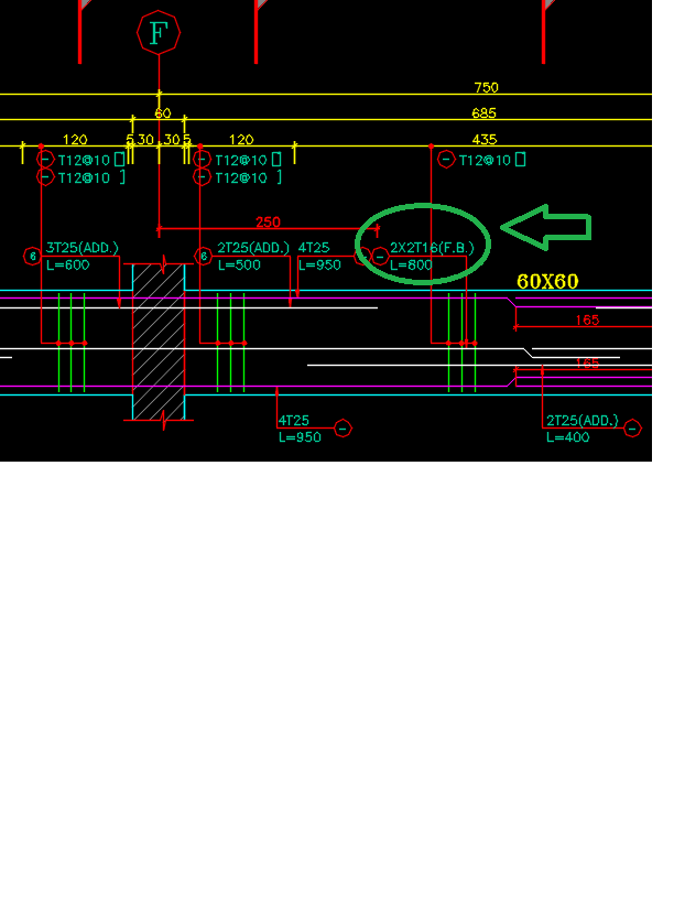
What is the best way to make a rebar table from a CAD drawing
khoshravan posted a topic in AutoCAD 2D Drafting, Object Properties & Interface
Dear Civil Engineers I have a drawing of rebars for a concrete beam as follows: Example: 2x2T16(F.B.)/L=800 It consists: 1-position numbers inside circle. They are not typed them in above drawing. 2- number of rebars: 2x2=4 for two side of the beam 3-T: to show t...