Search the Community
Showing results for tags 'bend'.
-
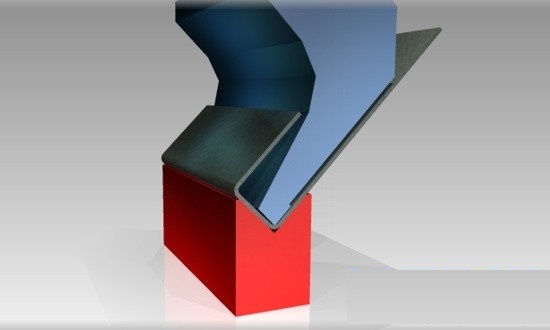
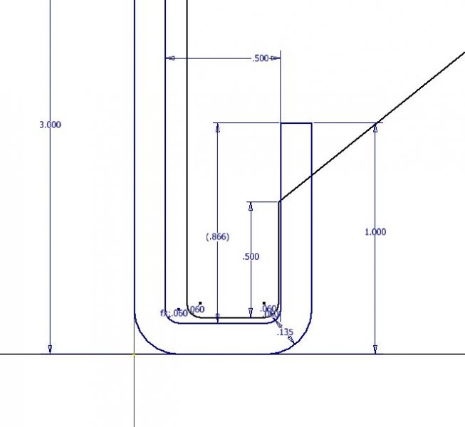
Started doing a bunch of sheet metal bending and trying to streamline our process. We have 50+ dies all labeled and organized on a rack, but at my computer we don't have reference to these dies other than the bend radius. My thought is that if we measure them all and make models we would be able to check to see if the die will clear the bend. Is there any smarter/faster/easier way to do this in inventor through the sheet metal bending tab or punch tool? This question came up when I made a part to get bent, see example image, but the die relief clashed against the part on the double bend. Rather than make a new die to fit my dimensions I have to redesign to fit our existing die parameters, ie make the lip smaller so the die clears. The hard way would be to just make a spreadsheet of the dimensions and verify the clearance, but I want something a bit more intuitive for future use. I think solidworks had something like this but I only used it at school years ago. Any fun suggestions? Thanks!
-
We had a custom part needed to be fabricated, guy bent bar stock to desired shape, gave to me. Now I am trying to reverse engineer to get manufacturing drawings and try to figure out the best way to get a straight length. I created a 3d sketch and sweep on the line for the shape. I can measure the straight lengths and arc lengths, but is there a better way to calculate this? I tried doing as sheet metal so I could create a flat pattern, but with round bar it doesn't seem logical, also tried making square and then fillet the edges but that didn't work well either. There are bends at different angles and planes so I am thinking about this for future use of wiring. For example, if I run wires through points with a 3d sketch how will I easily calculate how much wire I used? Saw lots of old posts but no solutions, thought this would be a good one to discuss further. HYDROLIC CYL LEVER BAR2.ipt