Search the Community
Showing results for 'catia'.
-
Hi all! Is there any way to import 3D/2D project from CATIA V5 to AutoCAD 2011? Thank you!
-
Hi, I'm a mechanical engineering student I'm working on a project of THSA and I have finished sizing the ball screw (lead 40mm nominal diameter 80mm) and know I want to know how to design it on catia because I did some research on google but no result. Here is the ball screw I've chosen(page 104 series 3426 the last one) : https://www.reliance.co.uk/wp-content/uploads/2017/12/Steinmeyer-Catalog-2017-EN-Reliance-web.pdf
-
I know that I should be able to open CATIA V5 drawings in AutoCAD Mechanical 13 or Autodesk Inventor Pro13. I've done it before but I am unable to do so at this time. Any suggestions? Is CAT alive or dead in AutoCAD? Thanks!
-

Problem after import from CATIA to Autocad
Skyuro posted a topic in AutoCAD 3D Modelling & Rendering
hello, i have a problem. First i did a model in CATIA after that i import it to AUtocad. Everything was ok with model but in zoom in model are discontinuities. -

Mechanical Engineering major...Inventor or Catia or Solidworks?
kingneptune117 posted a topic in Autodesk Inventor
I am a mechanical engineer, and i'm going to focus in aerospace. My ultimate goal is to work for boeing or some sort of aerospace company. I was considering learning AutoCAD but now I don't know. I heard programs like Inventor and Catia are more dominant in the aerospace/mechE industry. Help? I already have a bit of experience in inventor which I did enjoy more. -

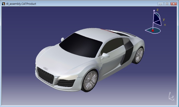
Free CATIA tutorial #8 (2010 New release) - Rebuild Audi R8 (1:1)
Dicksham posted a topic in Catch All
My CATIA tutorial 8- Rebuild Audi R8 (1:1) Highlights: - freeform 3D curves - surface merging & trimming - disappearing fillets - solid modeling - assembly design - design with a master model - design in context You can now download the complete training pdf (9MB) via http://www.dicksonsham.com Let's see the preview first. http://www.youtube.com/dicksham#p/u/3/LSBvrjlsPp8 -dickson sham
-
I am looking forward to joining courses in a good training institute . I would like to know if Pro-E , CATIA and Ansys is a good combination of courses to go about with or should i replace one of them with Solidworks or NXCAD/NXCAM .
-

which software is better among-AUTOCAD,PRO-E,CATIA,SOLIDEDGE & SOLID WORKS etc.
vikas saraswat posted a topic in AutoCAD Drawing Management & Output
Anybody Tell me which is better software among AUTOCAD,PRO-E, CATIA,solid work and SOLID EDGE etc and why? PRO-E and CATIA have got good future for me how i will decide it ? -
Anybody is familar with Solidworks + CATIA? i will like to know the difference & strong features of both.
-
Dear all, I am a Draftsman, using CAD & Max. now i am trying to Learn CATIA V5. need some help! hope you people will guide me. Best Regards M. Sohail
-
For those would learn catia can try my training materials: Tutorial 1 - Fundamentals (Toy excavator) Tutorial 2 - 2d to 3d (Mouse) Tutorial 3 - Design with analysis (deep fry basket) Tutorial 4 - FreeForm Surface (P51 Mustang) Tutorial 5 - Surface Modeling (Perfume Bottle) Tutorial 6 - Surface Modeling (Glasses) Tutorial 8 - Surface Modeling (Audi R8 Car) http://www.youtube.com/dicksham http://www.dicksonsham.com
-
hi. i am beginner to 3d design software.i have options to learn solidworks and catia. which one i should do??? please help......... cerrently i am pursuing b.tech in mechanical engineering..........
-

Excel PDM Spreadsheet Template for Product Data Management CAD file version control
Charliep posted a topic in AutoCAD General
I use AutoCAD and CATIA, but I work with a number of consultants and suppliers who use NX, SolidWorks, FreeCAD, etc., so working on a project we share many different file types and file versions. Does anybody have a spreadsheet / template for keeping track of changes to a CAD model during product development. It seems to me this would be an easy thing to keep in Excel, including data on the differences between versions of the CAD releases. I really don't want to develop the spreadsheet from scratch. Or maybe somebody can suggest a good software solution to keep track that doesn't require renting a server and hosting some database. I've looked at DDM and it looks ideal, but not looking to invest in a professional PDM right now. I like the idea of an Excel database because everybody already has Excel on their workstation, so there is no need to buy a bunch of licenses. -
Dear xperts I want to import my ACAD 2D DRAWINGS AND 3D MODELLINGS TO CATIA . How is Posiible ? Help me kind....
-
G'day all, Long time no see, hope all are well. Just a quicky, does anyone know where I could find a trial download of Catia V5? I have used our friend google but can't find anything yet and have even found a few forums saying a trial isn't available, but figured I would try and pick at the knowledge here and see if anyone has come across a download. A quick reply would be very much appreciated. Cheers All, Have a good 1.
-
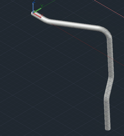
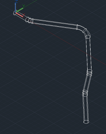
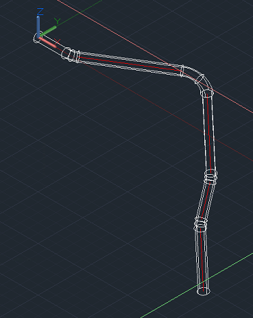
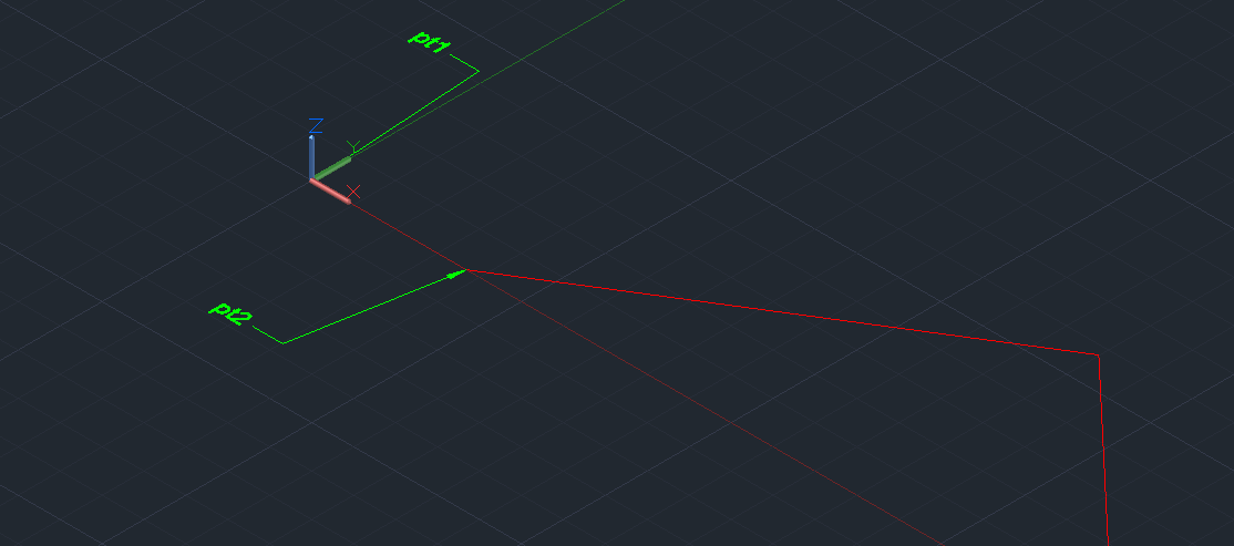
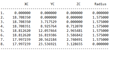
Ok...here is what I do manually. I take a solid like this: This is a solid bar, not a tube. I have no input on how its created, my customer does this. He uses Catia. I go through several steps to get it to something Autocad can read. In the end, I'm left with a solid. The shapes vary wildly. I then use the shade command to make it a wireframe, thusly: I then draw lines center to center on the straight parts of the tube like this (red lines) at this point, the solid no longer matters and can be erased, but that is optional. The bit that matters is that I zero- fillet these straight lines, thusly: At this point, I need to identify the cooridinates of each of the intersections and put that in a table. For instance, the first end point (pt 1) is obviously 0,0,0. The next point (pt2) is X = 1.8430 Y = 0.0000 Z = 0.0000. and so forth all the way to the end of the tube. This gives me a bend data table similar to this ( and this is not for this part, just an example): This data allows me to feed my cnc bender the info it needs to bend the tube. Sometimes my customers give me this bend data table, and the lisp that Roy wrote for me works perfectly to create the models. A different division of this same company however, sends me the Catia models, and I have to construct this bend data table myself by going through the steps I just detailed. No choice on how its drawn, all I get is the model. No dimensions, just the solid model. So...once again...not looking for a freebee...if someone can and will write a lisp that will do this, assuming its even possible, I will gladly trade an equitable amount of drafting work, in advance, for the lisp. If it can be done, great. If it can't, thats ok too. If you don't want to do it that way, that's fine too, make me an offer. Maybe we can work something out. If you don't want to do it at all, that's ok, just ignore this post. Pass on by, it's all good. Thanks again, and have a great weekend. Stay healthy my friends.
-
Well, you see, that's the problem. I didn't create the solids, my customer did. On top of that he uses Catia and exports them as a ".prt " file, which i import into Fusion to convert to an iges file, then into autocad to make a dwg (because trying to use Fusion for much else makes me want to run blindfolded into the traffic). This sounds like a joke, but sadly it's not. I can and have been doing this manually, so it's no big deal. Later tonight I'll post some drawings of the process I'm going through to make it easier to understand. May still not be possible, but I appreciate everyone's help and input. And they are not really tubes, just solids. They are not hollow, and for what we are doing they don't have to be. I dont know how Catia creates these things. In autocad, i would sweep a circle along a path and retain the path. They don't do that. I get what you see in the drawing.
-
I'm not sure you can go from .xml to .ply, but if you have Catia, you could save your catproduct as a catpart and then save to .stl format. See here: https://www.divbyz.com/convert-3d-models-to-stl-files-catia Then you can use Meshlab to convert the .stl file to .ply format.
-

Mechanical Engineering major...Inventor or Catia or Solidworks?
aoe2exp replied to kingneptune117's topic in Autodesk Inventor
"I am a mechanical engineer, and i'm going to focus in aerospace. My ultimate goal is to work for boeing or some sort of aerospace company. I was considering learning AutoCAD but now I don't know. I heard programs like Inventor and Catia are more dominant in the aerospace/mechE industry. Help? I already have a bit of experience in inventor which I did enjoy more. " I am a mechanical engineer as well that works on the aerospace industry. I have done so for the last 7 years specilizing in interiors and systems. I am experienced on Airbus and Boeing OEM designs. I've used Autocad for 7 years, CATIA for 5 and Inventor for 1.5 years. Based on my experience and my friends' I would recommend you the following software for you to learn: - Catia V5 (Try to learn Macros/CATIA programming if you can - there is a lot of money there) - SolidWorks - Autocad Boeing, Airbus and many of their suppliers use CATIA. CATIA is the way to go if you want to stay around and thrive in the aerospace industry. That is just how it is and that is where the money is. SW and ACAD are still used by much of the rest of suppliers so it would be good to learne them in order to appeal to a broader range of companies. Inventor is rarely used and I would not recommend spending any time on it. The main reason some companies use it is because it is cheap and the products they manufacture are not complex enough to justify an investment. -
This is correct, but I think AutoCAD was the first CAD program that didn't require a mainframe (can someone confirm this?). My grandfather remembers working in CATIA back int he 70's when he was an aerospace engineer: http://www.worldcadaccess.com/blog/2013/03/the-history-of-catia-computer-aided-tri-dimensional-interactive-application-by-its-founder-francis-b.html For those who are interested, my grandfather worked at LTV in the 70's and 80's in Grand Prairie, TX: http://www.gptx.org/about-us/history/history-of-aviation-in-grand-prairie He remembers clearly the CATIA platform, and remembers in the mid-late 80's, picking up AutoCAD when he was working as a consultant in his retirement (he retired in 1980, two years before I was born). He still has his AutoCAD manual on his bookshelf, I believe for version 9? But yeah, he's got great stories of CAD's original emergence. I love hearing about it. Even better stories about how to create an auxiliary view with nothing more than paper, pencil and some straight edges. -TZ
-
i want to export a 3d catia file to autocad how do you think it can be done
-
Sorry you couldn't get any help with this. I don't think we have any Catia users here. If you do a Google search for "Catia User Forum" you will find a few communities where you can ask your question. Good luck.
-
In my last job we designed boat hulls in Maxsurf and then exported iges surfaces to Catia for all the structures/styling/fitout/drawings etc. If we made a change to the hull we just re-exported the iges, brought it into Catia and then repointed any operations (trims, extracts, offsets etc.) from the old surface to the new one. In fact, there was a shortcut so you only have to repoint one operation, but thats not what my question is about... I'm now with a new company and we design boat hulls in Maxsurf, export iges surfaces and then use Rhino and AutoCAD for everything else, which is as painful as it sounds. I've persuaded them that we need to upgrade to the 21st century and the programs in the running are Inventor, Solidworks and ProE (budget won't stretch to Catia this time). My question is (I got there in the end!): Can you do the same replacing of pointed iges surfaces in Inventor as you can in Catia, and operations will update? I've been doing a lot of research and one thing I've learnt is, just because Catia can do something, doesn't mean the others can... Thanks in advance for your help
-

Mechanical Engineering major...Inventor or Catia or Solidworks?
Alex Moiceanu replied to kingneptune117's topic in Autodesk Inventor
For an aerospace engineer you should learn CATIA V5! Airbus, for example, used CATIA to design the Airbus A380 model. And this it's just aN inocent example of what's CATIA capable off. Inventor is used by small to medium companies for small projects, because it is much cheaper than CATIA. -

3D Interactive Assembly Instructions - SolidWorks Composer Alternative
cadasio posted a topic in Design Software
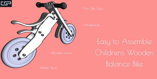
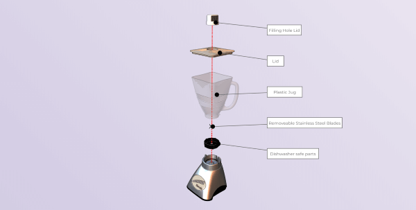
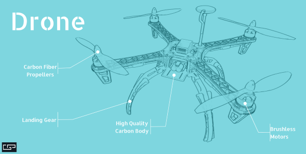
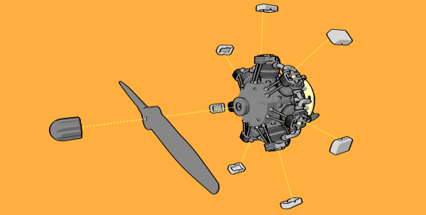
I thought it may be of interest to users of this forum that cadasio has just been released into early access and is available to use for free. cadasio is online software that will create assembly and service instructions, similar to those you may do with SolidWorks Composer (aka Catia Composer). However unlike SolidWorks Composer, cadasio focuses on creating an online project that you can share with anyone who has an internet connection, whether that's on desktop, tablet or mobile. We have plugins for the main CAD systems or you can upload neutral formats (STEP or OBJ). The projects are in 3D, so the end user can spin around and zoom in to get a greater understanding of your product and potentially reduce translation costs, and become more sustainable as you may not require lengthy paper printouts. Markup such as text, balloons, labels, pictures and arrows can all be added and well as hotspots and animations to make your products come to life and you can still save out 2D raster (png) images if you desire. Our showcase page has several examples to that demonstrate some of the capabilities of the software, and since its free why not come and try it out on your own products!