Leaderboard


Popular Content
Showing content with the highest reputation since 05/08/2026 in all areas
-
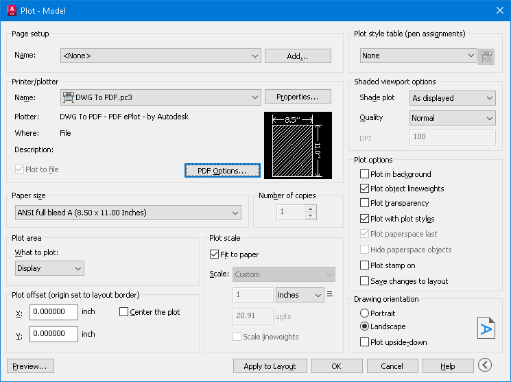
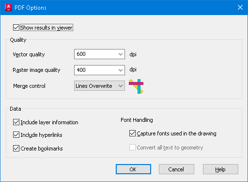
I meant to mention adding the (\U+200A). IIRC it's called a nonbreaking space. "Hairspace" sounds better IMO. I didn't try this, but one article mentioned to "Save As" or "Export to" PDF to kill the hyperlinks. My AutoCAD 2026 has the option to check Include Hyperlinks under PDF Options on the plot manager.
 2 points
 -
This code is so helpful to convert texts or mtexts to mleader. In the attachments the lisp file and cad file that has the problem I tied to solve. The cad file contains a huge amounts of elevations as texts and leaders that are exploded for landscape work , therefore this lisp can help with case like this Regards TBC- JOIN TEXT AND POLYLINES AND CONVERT THEM TO MLEADER OR MAKE IT MANUALLY.lsp BR FIN LVLS-1.dwg2 points
-
ah yes. https://www.cadtutor.net/forum/topic/98598-just-a-funny-basic-toolbar/2 points
-
Try this also. Seemed to work and makes a vector list code of objects. VECTORIZE.lsp2 points
-
That would be The Dragon, RLX maybe? He had a menu but not sure if that is the one you're thinking off? (I was impressed but been too busy this year to get into using it)2 points
-
Is this text in a TTF font or SHX? AutoCAD exports SHX fonts to searchable comments. If you turn that off (set PDFSHX system variable to 0), maybe the links will turn off too. SLW seems to be on the right track with PDF Options, try that first.1 point
-
I'll try that shortly and see if that works. PDF options didn't do much - mostly I think it is a PDF viewer thing (got into a whole word of space names yesterday, EM-space, EN-space, half EM, quarter EM... and so on depends on the website, never knew there were so many 'spaces')1 point
-
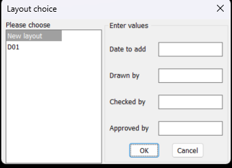
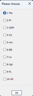
I have coded a dcl as per image but I can not get the list box answer I get the radio buttons as a list which is what I want. If ran as source code the listbox lsp works fine returning the items selected as a list. I am sure it is something very simple I am doing wrong. It will also help with a possible other post to know the answer. ; Big thanks to Alan J. Thompson, 09.23.08 / 05.17.10 (rewrite) ; For the original list box Listslect.lsp ; Modified by AlanH May 2026 to also have edit boxes (defun AH:xxxxxx1 ( / anslst1 anslts2 dcl_id key_lst keynum num x y) (setq fo (open (setq fn "D:\\acadtemp\\xxxxxx.dcl") "W")) (foreach x (list "roslist_select : dialog { " "label = \"Layout choice\" ; " ": row { " ": column { " ": list_box { " "label = \"Please choose\" ;" "key = \"lst1\" ;" "allow_accept = false ; " "height = 15 ; " "width = 25 ; " "multiple_select = true ; }" "}" " : boxed_column {" (strcat " label =" (chr 34) (nth 0 lst2) (chr 34) " ;") " width =25 ;" ) (write-line x fo) ) (setq num (/ (- (length lst2) 1) 4)) (setq x 0) (setq y 0) (repeat num (write-line "spacer_1 ;" fo) (write-line ": edit_box {" fo) (setq keynum (strcat "key" (rtos (setq y (+ Y 1)) 2 0))) (write-line (strcat " key = " (chr 34) keynum (chr 34) ";") fo) (write-line (strcat " label = " (chr 34) (nth (+ x 1) lst2) (chr 34) ";") fo) (write-line (strcat " edit_width = " (rtos (nth (+ x 2) lst2) 2 0) ";") fo) (write-line (strcat " edit_limit = " (rtos (nth (+ x 3) lst2) 2 0) ";") fo) (write-line " is_enabled = true ;" fo) (write-line " allow_accept=false ;" fo) (write-line " }" fo) (setq x (+ x 4)) ) (write-line "spacer ; " fo) (write-line "ok_cancel ;" fo) (write-line "}" fo) (write-line "}" fo) (write-line "}" fo) (close fo) (setq dcl_id (load_dialog fn)) (if (not (new_dialog "roslist_select" dcl_id)) (exit) ) (start_list "lst1") (mapcar (function add_list) lst1) (end_list) (set_tile "lst1" "0") (setq x 0) (setq y 0) (setq anslst2 '()) (repeat num (setq keynum (strcat "key" (rtos (setq y (+ Y 1)) 2 0))) (setq key_lst (cons keynum key_lst)) (set_tile keynum (nth (setq x (+ x 4)) lst2)) ) ; (mode_tile "key1" 2) (action_tile "accept" "(mapcar '(lambda (x) (setq anslst2 (cons (get_tile x) anslst2))) key_lst)(done_dialog)") (action_tile "lst1" "(setq anslst1 $value)") (action_tile "cancel" "(done_dialog)") (start_dialog) (unload_dialog dcl_id) ; (vla-file-delete fn) ) (setq lst1 (cons "New layout" (layoutlist))) (setq lst2 (list "Enter values " "Date to add" 15 14 "" "Drawn by" 15 14 "" "Checked by" 15 14 "" "Approved by" 15 14 "")) (AH:xxxxxx1) (if (= anslst1 nil)(alert "anslst1 is nil")(princ anslst1)) (princ "\n") (princ anslst2) ; anslst1 holds lst1 select values ; anslst2 holds the getval values
1 point
-
you have no action_tile assigned to your edit_boxes key1 ... key4 also anslst1 anslts2 have been declared local in your defun so values are not exposed outside your defun ; For the original list box Listslect.lsp ; Modified by AlanH May 2026 to also have edit boxes (defun AH:xxxxxx1 ( / fo fn dcl_id key_lst keynum num x y) ;; anslst1 anslts2 ;(setq fo (open (setq fn "D:\\acadtemp\\xxxxxx.dcl") "W")) (setq fo (open (setq fn "C:\\temp\\xxxxxx.dcl") "W")) (foreach x (list "roslist_select : dialog {label=\"Layout choice\";" ": row { " " : column { " " : list_box {label=\"Please choose\";" " key=\"lst1\";allow_accept=false;height=15;width=25;ultiple_select=true;}" "}" " : boxed_column {" (strcat "label=" (chr 34) (nth 0 lst2) (chr 34) " ;") " width =25;" ) (write-line x fo) ) (setq num (/ (- (length lst2) 1) 4)) (setq x 0) (setq y 0) (repeat num (write-line "spacer_1 ;" fo) (write-line ": edit_box {" fo) (setq keynum (strcat "key" (rtos (setq y (+ Y 1)) 2 0))) (write-line (strcat " key = " (chr 34) keynum (chr 34) ";") fo) (write-line (strcat " label = " (chr 34) (nth (+ x 1) lst2) (chr 34) ";") fo) (write-line (strcat " edit_width = " (rtos (nth (+ x 2) lst2) 2 0) ";") fo) (write-line (strcat " edit_limit = " (rtos (nth (+ x 3) lst2) 2 0) ";") fo) (write-line " is_enabled = true ;" fo) (write-line " allow_accept=false ;" fo) (write-line " }" fo) (setq x (+ x 4)) ) (write-line "spacer ; " fo) (write-line "ok_cancel ;" fo) (write-line "}" fo) (write-line "}" fo) (write-line "}" fo) (close fo) (setq dcl_id (load_dialog fn)) (if (not (new_dialog "roslist_select" dcl_id))(exit)) (start_list "lst1") (mapcar (function add_list) lst1) (end_list) (set_tile "lst1" "0") (setq x 0) (setq y 0) (setq anslst2 '()) (repeat num (setq keynum (strcat "key" (rtos (setq y (+ Y 1)) 2 0))) (setq key_lst (cons keynum key_lst)) (set_tile keynum (nth (setq x (+ x 4)) lst2)) ) ; (mode_tile "key1" 2) ;(action_tile "accept" "(mapcar '(lambda (x) (setq anslst2 (cons (get_tile x) anslst2))) key_lst)(done_dialog)") (action_tile "accept" "(read_tiles key_lst)(done_dialog)") (action_tile "lst1" "(setq anslst1 $value)") (action_tile "cancel" "(done_dialog)") (start_dialog) (unload_dialog dcl_id) ; (if (setq fn (findfile fn)) (startapp "notepad" fn)) ; (vla-file-delete fn) (princ) ) ;;; end defun (defun read_tiles (key_lst) (foreach key key_lst (setq anslst2 (cons (cons key (get_tile key)) anslst2)))) ;;; hit & run (setq lst1 (cons "New layout" (layoutlist))) (setq lst2 (list "Enter values " "Date to add" 15 14 "" "Drawn by" 15 14 "" "Checked by" 15 14 "" "Approved by" 15 14 "")) (AH:xxxxxx1) (if (= anslst1 nil)(alert "anslst1 is nil")(princ anslst1)) (princ "\n") (princ anslst2) ; anslst1 holds lst1 select values ; anslst2 holds the getval values1 point
-
Thanks SLW210 for looking for me, a font of all knowledge1 point
-
The project specifications are limiting us to Arial font, and a set format for the text strings. It isn't a CAD issue but a PDF reader issue - and we cannot control what others use to look at files. So not a lot we can actually do with the plotting to make it behave as it should unfortunately. So many texts that start with the format qwe.rty.uio..... are seen as hyperlinks in the PDF. Our work around - for anyone following this - is to use 'hairspace' after the '.' (\U+200A) which you can see is there if you know it is there else so far works.1 point
-
What reader do you use? Should be an option to turn off automatic link detection. Post a sample PDF and DWG. You may need to use brackets, parenthesis, different font, etc. for the file names, I do believe that is the way it works with the "." in the word. P.S. I just checked Adobe sight, supposedly certain fonts should make them work. Monospaced Fonts? Which ones have you tried?1 point
-
Good day I would like to share this lisp for anyone need it Regards extcoord-extract_coords of anything -REV20.lsp1 point
-
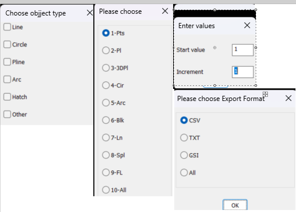
Yes Ai is being used more, but sometimes does not work, that's when you need lisp experience to work out what is wrong. But paste that you wrote it using AI still put your name to it. I would build a big DCL. Oops should have been 4 columns but you get the idea. Yes can use the list box instead of toggle buttons. Just pasted each option into one image as a guide to how it should look. Oh yeah if your using object point numbers then should include a function that finds the last object number used if your selecting single objects at a time.
1 point
-
A few comments. You have not put your name and date to code, say add at that start. You can write direct to Excel rather than opening a csv. Can help with that. You can replace the Initget with the attached. Multi radio buttons.lsp Other methods available also. Same with the "point markers" Multi toggles.lsp Also for input values strings or numbers Multi GETVALS.lsp if (not AH:Butts)(load "Multi radio buttons.lsp")) ; loads the program if not loaded already (if (= but nil)(setq but 1)) ; this is needed to set default button (setq lst (list "Please choose" "1-Pts" "2-Pl" "3-3DPl" "4-Cir" "5-Arc" "6-Blk" "7-Ln" "8-Spl" "9-FL" "10-All")) (setq ans (ah:butts but "V" lst)) All 3 options can be made into a single DCL.
1 point
-
From HERE. Also mentioned in that post was Terry Millers GetVectors, but he has a new site now. AutoLISP Code1 point
-
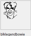
You could try these, the first one, test, will return lists for each line with the 4 values for the 2 end points (x1, y1, x2, y2). You need to also select a reference point to measure these points to. I tend to draw the thumbnail in a 75x75 square, reference point is top left corner and all the thumbnail entities are lines - nothing else - function name test The second one I haven't adjusted, copied straight from my library, blockthumbrecord, select the lines, select the reference point and it will return some results in a new notepad window... so not been adjusted you might need to add a function in there (LM: functions from Lee Macs website). Also the notepad will add in other stuff that is handy for me - a good learning exercise to look at the code and adjust it so it works for you. Both will give you sets of points for each line in a selection which you can copy and paste for your needs. Note that the vector graphics cannot do fractions, so maybe best set your snaps and grid to '1' and to get a smooth curve, a few short lines and make sure that the ends all touch. (defun c:test ( / ) (defun LM:round ( n ) (fix (+ n (if (minusp n) -0.5 0.5))) ) (princ "\nSelect LINES for thumbnail: ") ;;Get entities (setq ss (ssget '((0 . "LINE")))) (if (not ss) ;check for nil selection set (progn (princ "Nothing selected.") (exit) ) ;end progn ) ;end if ;;get list of entities (setq LinesList (list)) (setq acount 0) (setq BasePoint (getpoint "\Select Top Left Corner of Tumbnail (75x75 square)")) (setq BasePoint (reverse (cdr (reverse BasePoint)))) (while (< acount (sslength ss)) ;loop for every entity in the set (setq en (ssname ss acount)) ;get entity name (setq ed (entget en)) ;get entity definition (setq pt1 (reverse (cdr (reverse (cdr (assoc 10 ed)))))) ;; X and Y only (setq pt1 (mapcar '- BasePoint pt1)) ;; Shift by basepoint (setq pt1 (mapcar 'LM:round (mapcar 'abs pt1))) ;; Absolute value rounded to nearest 1 (setq pt1 (list (rtos (car pt1) 2 0) (rtos (cadr pt1) 2 0) )) ;; List items to strings (setq pt2 (reverse (cdr (reverse (cdr (assoc 11 ed)))))) ;; X and y Only (setq pt2 (mapcar '- BasePoint pt2)) ;; Shift by basepoint (setq pt2 (mapcar 'LM:round (mapcar 'abs pt2))) ;; Absolute value rounded to nearest 1 (setq pt2 (list (rtos (car pt2) 2 0) (rtos (cadr pt2) 2 0) )) ;; List items to strings (setq pt1 (append pt1 pt2)) ;; Create thumbnail definition line (setq LinesList (append LinesList (list pt1)) ) ;; Add definition line to thumb. definition (setq acount (+ acount 1)) ) ;;end while LinesList ) (defun c:blockThumbrecord ( / ss LinesList acount en ed pt1 pt2 tempblock f ) ;;Opens notepad wth lines coordinates (defun LM:lst->str ( lst del / str ) (setq str (car lst)) (foreach itm (cdr lst) (setq str (strcat str del itm))) str ) ;;Get entities (setq ss (ssget '((0 . "LINE")))) (if (not ss) ;check for nil selection set (progn (princ "Nothing selected.") (exit) ) ;end progn ) ;end if ;;get list of entities (setq LinesList (list)) (setq acount 0) (while (< acount (sslength ss)) ;loop for every entity in the set (setq en (ssname ss acount)) ;get entity name (setq ed (entget en)) ;get entity definition (setq pt1 (cdr (assoc 10 ed))) (setq pt1 (list "list" (rtos (abs (car pt1)) 2 0) (rtos (abs (cadr pt1)) 2 0) )) (setq pt2 (cdr (assoc 11 ed))) (setq pt1 (append pt1 (list (rtos (abs (car pt2)) 2 0) (rtos (abs (cadr pt2)) 2 0) "TxCol"))) (setq LinesList (append LinesList (list pt1)) ) (setq acount (+ acount 1)) ) ;;end while ;;write to a temp file (if (strcat (getvar "TEMPPREFIX") "Thumbnail.txt")(vl-file-delete (strcat (getvar "TEMPPREFIX") "Thumbnail.txt"))) (setq tempblock (strcat (getvar "TEMPPREFIX") "Thumbnail.txt")) ;;add check if this exists (setq f (open tempblock "w")) ;;open file (write-line " (Defun Sel--**FUNCTIONNAME**-- ( origin BgCol TxCol ImgTile Control / BlkList return) " f) (write-line " (if (= Control \"Vector\") " f) (write-line " (progn " f) (write-line " (start_image ImgTile) " f) (write-line " (fill_image (- origin 0) 0 (+ origin 85) 85 BgCol) " f) (write-line " (setq BlkList (list " f) (setq acount 0) (while (< acount (length LinesList)) (write-line (strcat "(" (LM:lst->str (nth acount LinesList) " ") ")" ) f) (setq acount (+ acount 1)) ) (write-line " )) ; end setq end list" f) (write-line " (setq Xoff 0)(setq YOff 0)" f) (write-line " (CreateVector BlkList XOff YOff TxCol)" f) (write-line " (end_image)" f) (write-line " ); end progn" f) (write-line " (setq Return \"--**FUNCTION NAME TO INSERT BLOCK**--\")" f) (write-line " ) ; end if" f) (write-line " )" f) (write-line "" f) (write-line "; -OK- ;" f) (close f) ;;open notepad & file ;; (startapp "c:/windows/notepad.exe" tempblock) (vl-catch-all-apply (function (lambda () (setq obj (vlax-get-or-create-object "WScript.Shell")) (vlax-invoke obj 'Run (strcat "c:/windows/notepad.exe \"" tempblock "\"")) ;; or notepad++ if that is used. (setvar 'cmdecho 0) (vlax-invoke obj 'AppActivate "Notepad") ; Title bar name of application. ++ for notepad++ but still works? ) ) ) (if obj (vlax-release-object obj)) (princ) ) These should make it possible to easily get the coordinates to make something like this as a thumbnail: (The Engineers keep asking me to add a legend.... so I do) The second LISP makes up the code I need for my block selection routine, thumbnail graphic, saved in the code, see the image I like, click and paste
1 point
-
Didn't someone have a lisp that created a menu system in model space ? on the right side of the current view.1 point
-
As far as I remember the numbers are pairs of points, in your '(' 18 ad 17, 16 and 15..... with the X coordinate to the left and Y to the TOP (unlike usual CAD where Y is counted from the bottom) So your code has an odd number of numbers - I think they need an even number. CAD is off for the evening now, but that might help. You could also post the link to Lees code - usually there is an explanation in there, and also perhaps a screen shot of what you are getting or any errors.1 point
-
AutoCAD has PDFSHXTEXT to convert the vector lines/arcs that once were SHX texts back to texts. Post the converted PDF file from ZWCAD. Sounds like you need to use something better than ZWCAD if it isn't capable of doing what you need. This still goes back to you need to use TTFs.1 point
-
;list select dialog ;create a temp DCL multi-select list dialog from provided list ;value is returned in list form, DCL file is deleted when finished ;example: (setq the_list (AT:listselect "This is my list title" "Select items to make a list" "25" "30" "true" (list "object 1" "object 2" "object 3")) ;if mytitle is longer than defined width, the width will be ignored and it will fit to title string ;if mylabel is longer than defined width, mylabel will be truncated ;myheight and mywidth must be strings, not numbers ;mymultiselect must either be "true" or "false" (true for multi, false for single) ;created by: alan thompson, 9.23.08 ;some coding borrowed from http://www.jefferypsanders.com (thanks for the DCL examples) (defun AT:ListSelect ( mytitle ;title for dialog box mylabel ;label right above list box myheight ;height of dialog box !!*MUST BE STRING*!! mywidth ;width of dialog box !!*MUST BE STRING*!! mymultiselect ;"true" for multiselect, "false" for single select mylist ;list to display in list box / retlist readlist count item savevars fn fo valuestr dcl_id ) (defun saveVars(/ readlist count item) (setq retList(list)) (setq readlist(get_tile "mylist")) (setq count 1) (while (setq item (read readlist)) (setq retlist(append retList (list (nth item myList)))) (while (and (/= " " (substr readlist count 1)) (/= "" (substr readlist count 1)) ) (setq count (1+ count)) ) (setq readlist (substr readlist count)) ) );defun (setq fn (vl-filename-mktemp "" "" ".dcl")) (setq fo (open fn "w")) (setq valuestr (strcat "value = \"" mytitle "\";")) (write-line (strcat "list_select : dialog { label = \"" mytitle "\";") fo) (write-line (strcat " : column { : row { : boxed_column { : list_box { label =\"" mylabel "\"; key = \"mylist\"; allow_accept = true; height = " myheight "; width = " mywidth "; multiple_select = " mymultiselect "; fixed_width_font = false; value = \"0\"; } } } : row { : boxed_row { : button { key = \"accept\"; label = \" Okay \"; is_default = true; } : button { key = \"cancel\"; label = \" Cancel \"; is_default = false; is_cancel = true; } } } } }") fo) (close fo) (setq dcl_id (load_dialog fn)) (new_dialog "list_select" dcl_id) (start_list "mylist" 3) (mapcar 'add_list myList) (end_list) (action_tile "cancel" "(setq ddiag 1)(done_dialog)") (action_tile "accept" "(setq ddiag 2)(saveVars)(done_dialog)") (start_dialog) (if (= ddiag 1) (setq retlist nil) ) (unload_dialog dcl_id) (vl-file-delete fn) retlist );defun1 point
-
Thanks, will check that out later.1 point