Leaderboard


Popular Content
Showing content with the highest reputation since 07/27/2026 in Posts
-
So did you ever figure out how to do it, OP? I don't know how someone doesn't manually save like every 5 min. I can tell now that this is not a natural reaction for everyone. I am a millennial and it's been metaphorically beaten in my head throughout my all school years to save often. I save after every small bit of changes that I make. Hope you found a way that works for you, though!!2 points
-
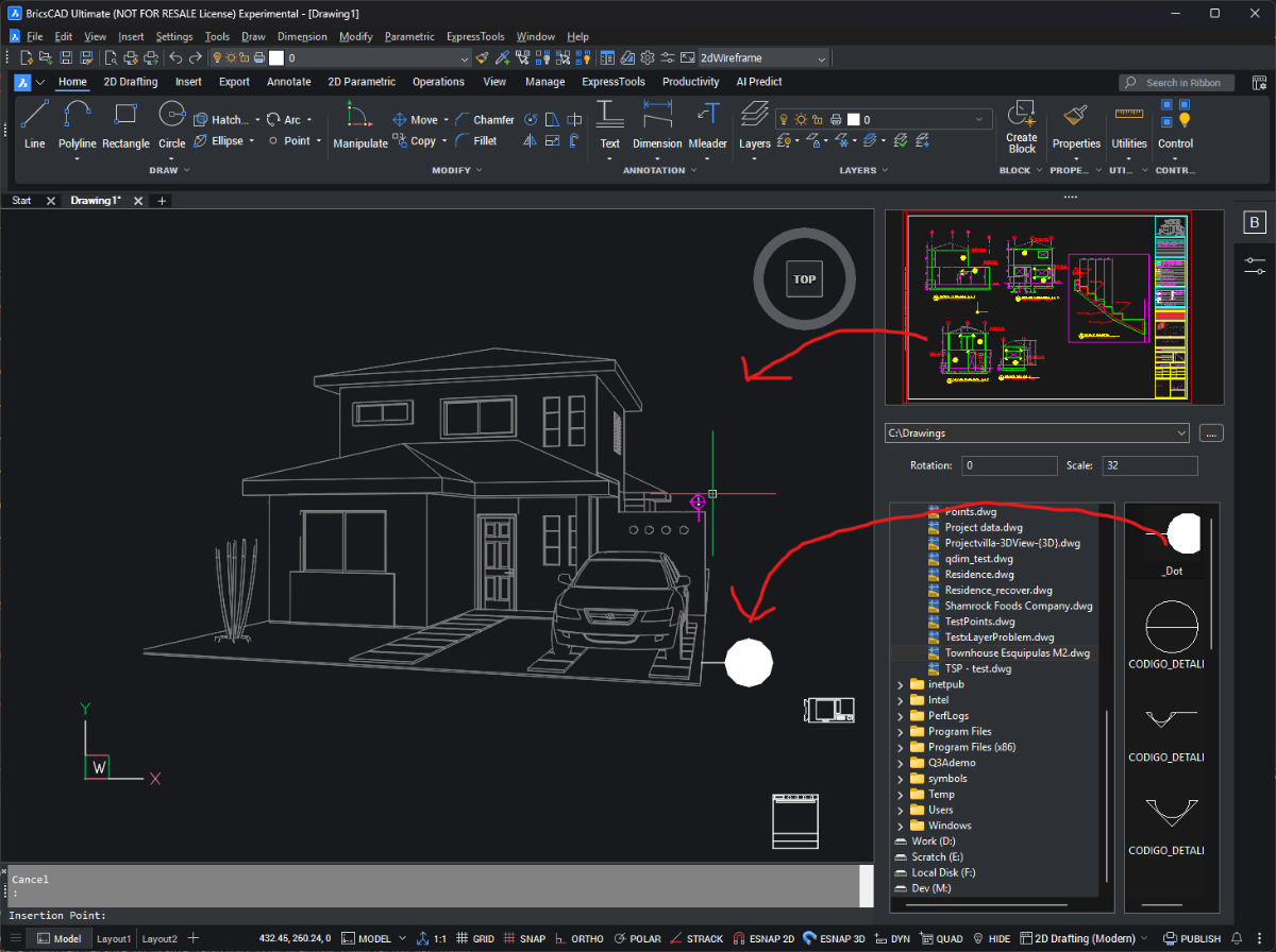
I posted this at the swamp, this is pretty cool Proof of concept (V25, V26, V27Beta) - appload BrxBlockManXX.brx - type blockman at the prompt - select a drawing from the directory control - double click or drag a block from the List control to the current drawing - double click the main preview to insert the whole drawing - click the open folder button to add your favorite folder(s) - use the dropdown to navigate to a favorite folder - right click on a dwg to open it let me know if it crashes lol edit, posted the source and binaries here https://github.com/CEXT-Dan/BrxBlockMan
 1 point
 -
@Danielm103 has updated the code and its running under Bricscad and is very impressive, I am sure the updated code will be posted here soon.1 point
-
I think the bottom line is how much are you prepared to lose in production time ? A autosave of say 1/2 hour to me sounds reasonable. Were I worked we had a power failure, a IT server disconnect. The power out showed how often people saved their work, renaming the sv$ helped. Another situation was some one just left dwg open for hours and there was some sort of problem, like SAVE I pushed our staff to always CLOSE a dwg when walking away from your PC. Yes you can go the toilet or get a coffee.1 point
-
You have to make two Field, once for Distance of Block, then Once for Arrray Object (item or column * row). Cause an Array Object now is include all block, all Field of length in per Array is fixed1 point
-
from pyrx import Ap, Ax, Db, Ed, Ge, Br def getAllFieldsIds(db: Db.Database): ids: list[Db.ObjectId] = [] nod = Db.Dictionary(db.namedObjectsDictionaryId()) fieldListId = nod.getAt("ACAD_FIELDLIST") fieldList = Db.Core.entGet(fieldListId) for fieldItem in fieldList: if fieldItem[0] == 330 and fieldItem[1].isDerivedFrom(Db.Field.desc()): ids.append(fieldItem[1]) return set(ids) @Ap.Command() def doit() -> None: db = Db.curDb() field_ids = getAllFieldsIds(db) for id in field_ids: field = Db.Field(id, Db.OpenMode.kForRead) fmt = field.getFormat() if 'pr3' in fmt: field.upgradeOpen() new_fmt = fmt.replace('pr3', 'pr4') field.setFormat(new_fmt) field.evaluate(Db.FieldEvalContext.kDemand, db) print(f"Updated field format from {fmt} to {new_fmt}")1 point
-
@CamDuy gave it a try it appears to only look for a text object the OP wants an attribute in a block also to be updated.1 point
-
Agreed. I am 100% on the side of [turn Autosave OFF] and use one of the many ways to save your data file every time you do something you don't want to lose.1 point
-
@RobDraw - or 8 more years later ?1 point
-
That is cool! But didn't AutoCAD 2027 released something tiny bit similar (project workspace?)1 point
-
CopyRenameBlockV1-5_byCamDuy.lsp Try using this file. @Nikon1 point
-
Nice Lisp VicoWang! This looks like a great solution to the dreaded startup suite, some suggestions; Is it possible to have the "Asset Name" be the file name by default? Could the "Version" field default to 0?1 point
-
We use Civil 3D, so we have more tools. Typically we get a batch of points in state plane coordinates. That means you can draw a line anywhere along the Y axis of those coordinates and get a fairly accurate North. It's not totally accurate because, obviously, that same vertical line is parallel at the ends of your state, which can be hundreds of miles apart. That's what a datum is for, I guess, to reconcile the grid with the surface of the Earth. This seems like a simple problem, but it's a nightmare if you don't have enough data. What I'll typically do is get a screen grab from an aerial map, making sure it's oriented to North, at a known scale, with a graphic scale included. Add that image to the drawing as an Xref at rotation 0. Scale it so that the graphic scale is correct. Then the fun part: find locations that match your drawing and line them up. Then the nightmare part: keep in mind that aerial images aren't always taken from directly above that area, so there's going to be some skew--and you have no way of knowing what that skew factor is. Sometimes you have to decide which points are more important to get right and let the rest be off. There's a command named ALIGN, which is very handy here: pick two or three points from the image and the corresponding points from the drawing; decide whether to scale the image; and watch the magic. With a drone you could get an image from a known spot, but not everyone has access to a drone. Other strategies: look for benchmarks in your drawing. In the US there's a system of markers placed by the Geodetic Survey. Surveyors often begin their locating from a benchmark, geodetic or otherwise. What you're trying to do is find three points that will define a plane. The other strategy only works if you know some property corners or can locate them: get a plat (not a deed, those cost money) for a piece of property. It will include bearings and distances for each border line. That gives you distance and direction between your property corners, so you can define your plane. Of course all these strategies depend on the drawing being in World UCS. You sometimes find a Plan North, and you can create a UCS to match that. Orienting the drawing to some other UCS will lead to problems down the line, I've been there.1 point
-
Did not look to hard but an obvious one for me was. (setq road-text-layer "Road-Labels") ; The layer where the text numbers will go If layer "Road=labels" does not exist then program will crash, IF does not exist so just "Make" the layer. In lots of code I am writing I will take advantage of a global defun that is in another preloaded lisp, it has a checklayer function. This something like all you would need. (chklayer "Road-Label" 1 "Continous") (setq road-text-layer "Road-Labels") Agree with other post label at mid point, Using vertices can get be returned form a pline that is drawn in wrong direction than you think. Yours (setq current-dist-start (vlax-curve-getDistAtPoint road-entity start-pt)) I have a swap or flip a pline so start direction is from end selected. But using mid solves this. May not need this function if using mid. There is VL get coordinates that returns all the vertice XYZ. (defun helper-find-and-sort-intersections (setq lst (vlax-safearray->list (vlax-variant-value (vla-get-coordinates obj)))) Also this for pline vertice points, thanks to lee--mac. (setq plent (entsel "\nPick rectang")) (if plent (setq co-ord (mapcar 'cdr (vl-remove-if-not '(lambda (x) (= (car x) 10)) (entget (car plent)))))) (princ co-ord) Just another idea when doing add more items to an existing drawing, do a "does the labels exist already" ? If so then get them all and find last label then add one to it. You have a layer name so can ssget MTEXT for that layer. Just me I don't tend to do this, make a list of entities, then process that list. It's a personal preference (while (setq entity (ssname road-ss i)) (setq global:all-roads (cons entity global:all-roads)) (setq i (1+ i)) ) I just act on the current entity returned by the while or a Repeat and do the labelling of that entity. This is sort of double handling the SSGET if you use Pick PIck Pick method the selection set should be in the pick order (setq first-road (car (entsel "\nSelect the FIRST road (from your selection): "))) Otherwise use a Pick and label method it will be fast. The label will appear as fast as you pick. Maybe even a dual method pick and window. Having a bit of a look I think code can be shortened a lot.1 point
-
@VicoWang I don't do anything with the cloud but I know some of my clients are going that way for various reasons, in the very simple way the Install.lsp works there is no reason why the programs etc can not be loaded to the cloud. You only need correct support paths hopefully set, I don't use the cloud. One other thing is we had laptops where I worked, so when outside in the field the user would select the correct icon on the desktop, we had two icons "In office" and "Out of office" then the correct profile was loaded. The "out of office" would look on the laptop for programs etc, Yes had a slightly different set of menu's. The profile choice is in the ICON properties.1 point
-
Hello. May I make a suggestion? Perhaps you could simplify the user prompts from this: (setq first-road (car (entsel "\nSelect the FIRST road (from your selection): "))) (setq start-point (getpoint "\nClick near the START point of the first road: ")) to a single prompt: (setq first-road (car (setq es (entsel "\nSelect the FIRST road near the START point (from your selection): "))) start-point (cadr es) ) Also, your code calculates the midpoint based on the number of vertices rather than on the actual distance along the road. You might prefer to place the label at the geometric midpoint by replacing this: (setq mid-param (/ (vlax-curve-getEndParam road-entity) 2.0)) with this: (setq total-dist (vlax-curve-getDistAtParam road-entity (vlax-curve-getEndParam road-entity)) mid-param (vlax-curve-getParamAtDist road-entity (/ total-dist 2.0)) )1 point
-
Yes need a much better realistic sample dwg with say a couple of different scenarios, array,non array and so on, even different lengths. There is a way of getting array info, you read the 1st object for properties, then the numbers in the row and column values.1 point
-
Have you tried using a multi-line? This looks like it is comprised of 3 lines (2-continuous either side of a width adjusted polyline). You could mimic this with the three lines, simply offsetting the centerline and changing the ltype to continuous and the width to 0.1 point