Leaderboard


Popular Content
Showing content with the highest reputation on 06/12/2024 in all areas
-
You probably all ready know this, but for others following this. If you use: (entget (car (entsel))) in the command line it will return the entity DXF code description for that (there are LISPs that do the same). Copy this and remove the '-1', '5' and '330' entries - this is the basis for entmake or entmakex (entmakex if you want to use the entity as in (setq MyNewEnt (entmakex (list ..... ))) ). If you entmake what you copy you will create a copy of the original entity. Anyway point being, if you are struggling with entmake, create a template entity as you want it, (entget.... ) it then you can modify the entmake code as required. Note that sometimes the order of the dxf codes is important too. I would ;; out parts so they can go back in again and check that it all still works OK. Sometimes what you make needs an attsync, redraw or regen to show the entity properly - blocks tend to like an attsync2 points
-
Hi, I have just started learning AutoLISP programming by watching YouTube videos so I can improve my routine work by automation with the help of AutoLISP programming. My aim is to get fully automation in exporting co-ordinates from AutoCAD drawing into excel, so step by step I would like to achieve this task. What I have learned so far to create a AutoLISP program to read co-ordinates of circles in attached drawing and to show as text at centre points of circles. I have created the program but I need help how to get co-ordinates by setting up UCS at bottom of each objects (no's 01 to 05). Coordinates.dwg AutoLISP-Coordinates.docx1 point
-
I tended to learn from AfraLISP - SLW210 link. For alignment you might want to consider a combination of row and column codes with a width setting. This is for an example, taken from a grid DCL: an image, under that and lined up a text description, 'next' row is the same again (is actually row 3 because of the text description). (write-line " :boxed_column { width = 25; alignment = top;" fo) (write-line " :row {alignment = top;" fo) (write-line " :column {width = 15; :image_button {key = Im0; width = 9; height = 5; color = dialog_background; allow_accept = true; alignment = centered;}}" fo) (write-line " :column {width = 15; :image_button {key = Im1; width = 10; height = 7; color = dialog_background; allow_accept = true;}}" fo) (write-line " }" fo) ; end row (write-line " :row {alignment = top;" fo) (write-line " :column {width = 15; :text { key = \"Txt0\"; label = \"Func.\"; width = 9;}}" fo) (write-line " :column {width = 15; :text { key = \"Txt1\"; label = \"Func.\"; width = 9;}}" fo) (write-line " }" fo) ; end row (write-line " :row {alignment = top;" fo) (write-line " :column {width = 15; :image_button {key = Im4; width = 10; height = 7; color = dialog_background; allow_accept = true;}}" fo) (write-line " :column {width = 15; :image_button {key = Im5; width = 10; height = 7; color = dialog_background; allow_accept = true;}}" fo) (write-line " }" fo) ; end row (write-line " :row {alignment = top;" fo) (write-line " :column {width = 15; :text { key = \"Txt4\"; label = \"Func.\"; width = 9;}}" fo) (write-line " :column {width = 15; :text { key = \"Txt5\"; label = \"Func.\"; width = 9;}}" fo) (write-line " }" fo) ; end row (write-line " }" fo) ; end boxed column In yours perhaps the 'command layer colour linetype' should also be split into 4 columns in a single row It all becomes mental fun when you want columns and rows spanning multiple other rows and columns to get it all lining up. Edited code for readability1 point
-
With a list_box tile, you need to use the "tabs" attribute: https://help.autodesk.com/view/ACD/2024/ENU/index.html?guid=GUID-816B0089-B281-4EB8-8CED-2F8617E812631 point
-
(cons 70 1) to be invisible1 point
-
For the attributes try this format: (entmakex (list (cons 0 "ATTDEF") (cons 100 "AcDbEntity") (cons 8 "0") (cons 100 "AcDbText") (cons 10 '(0.0 0.0 0.0) ) (cons 40 2) (cons 1 "Default") (cons 100 "AcDbAttributeDefinition") (cons 3 "Prompt") (cons 2 "TAG") (cons 70 0) )) and also I think for attributes put in an attsync when the block is inserted1 point
-
You need to add dxf group code 3 when creating block, its for prompt i think. Here is edited code I just copied string of dxf code 2, works for me ;;; Copied to window at 2:06 PM 6/12/24 (defun cssabl_blk (pt station height /) (setvar "CMDECHO" 0) (if (not (tblsearch "BLOCK" "CSSABL")) ;_ _not (progn (entmake (list (cons 0 "BLOCK") (cons 2 "CSSABL") (cons 70 2) (cons 10 '(0. 0. 0.)) ) ;_ _list ) ;_ _entmake (entmake (list (cons 0 "POINT") (cons 8 "0") (cons 10 '(0. 0. 0.)) ) ;_ _list ) ;_ _entmake (entmake (list (cons 0 "ATTDEF") (cons 8 "0") (cons 10 '(0.0 0.0 0.0)) (cons 70 0) (cons 1 "") (cons 2 "STATION") (cons 3 "STATION") (cons 40 2.0) ) ;_ _list ) ;_ _entmake (entmake (list (cons 0 "ATTDEF") (cons 8 "0") (cons 10 '(0.0 0.0 0.0)) (cons 70 0) (cons 1 "") (cons 2 "HEIGHT") (cons 3 "HEIGHT") (cons 40 2.0) ) ;_ _list ) ;_ _entmake (entmake (list (cons 0 "ENDBLK") (cons 8 "0") ) ;_ _list ) ;_ _entmake ) ;_ _progn ) ;_ _if (entmake (list (cons 0 "INSERT") (cons 2 "CSSABL") (cons 10 pt) (cons 66 1) ) ;_ _list ) ;_ _entmake (entmake (list (cons 0 "ATTRIB") (cons 10 pt) (cons 1 station) (cons 2 "STATION") (cons 40 2.0) (cons 70 0) ) ;_ _list ) (entmake (list (cons 0 "ATTRIB") (cons 10 pt) (cons 1 height) (cons 2 "HEIGHT") (cons 40 2.0) (cons 70 0) ) ;_ _list ) ;_ _entmake (entmake (list (cons 0 "SEQEND") ) ;_ _list ) ;_ _entmake );defun ;;; End of text1 point
-
Where is your .dcl? Read... DCL alignment column - AutoLISP, Visual LISP & DCL - AutoCAD Forums (cadtutor.net) DCL Tile Attributes-Alignment (afralisp.net) Dialog Box Layout - Page I (afralisp.net)1 point
-
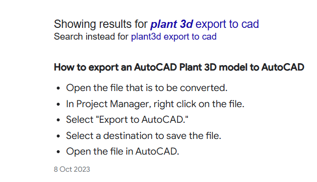
Should be able to do but will get a message about proxy objects, not sure if plant3d has the option exporttocad etc which means take a plant3d dwg and export to a plain CAD dwg. Wow there is this software called Google may be try it. I don't have Plant3d so not tested.
 1 point
 -
Essentially you need to obtain three orthogonal vectors representing the transformation from the first set of points to the second set of points - such vectors will then form the columns of the 3x3 upper-left component of your transformation matrix. You would then apply such matrix to your original point and calculate the difference from the target point - such difference is the translation vector of your 4x4 matrix. Google 'change of basis matrix' for more information on this subject.1 point
-
I may be totally misunderstanding the question, but it sounds like what they do in Blender with matrix algebra. To apply successive transformations, they simply multiply (dot product) each one by the next. The only caveat is to apply them in the correct order. If that doesn't help, please elaborate.1 point
-
I did manage to get this working. I am not sure if attreq was set properly but it is now. There is a difference in prompts between dynamic and non dynamic blocks. This was the part that was messing me up. Thanks everyone for helping out. BIGAL for ssget idea (this will be implemented in the next version) mhupp for showing me the typos. (I always forget to quote or not quote numbers) rlx for point out attreq variable (did not know about this variable before) working code (defun c:spool_labels ( / prefix cnt oldclayer oldattdia oldattreq pt) (setq prefix (getstring t "\nENTER PREFIX: ") cnt (getint "\nENTER INTEGER TO START: ") ;; value to start the counter at oldclayer (getvar 'clayer) oldattdia (getvar 'attdia) oldattreq (getvar 'attreq) ) ;; Turn dialog off for the attributes (setvar 'attdia 0) (setvar 'attreq 1) ;; Create layer for the blocks to be inserted on (command "-layer" "make" "Blocks-Spool Label" "color" "magenta" "" "") (while (setq pt (getpoint "\nPICK INSERTION POINT: ")) ;; get insertion point for block (command ".-insert" ;; command to insert a dynamic block "_MP Spool Label" ;; name of block to insert "_non" pt ;; insertion point for block "1" ;; x scale value for the block "0" ;; rotation value for the block ;; concatenate the prefix to the counter for the name (strcase (strcat prefix (itoa cnt))) ) ;; increment the counter (setq cnt (1+ cnt)) ) ;; restore change system values (setvar 'clayer oldclayer) (setvar 'attdia oldattdia) (setvar 'attreq oldattreq) (princ) ) attaching dynamic block _MP Spool Label.dwg1 point
-
I thought I would post the Drawing to DXF batch converter, as well as the others I have worked on. All thanks go to the originator and the others that have made modifications and updates, I did very little. I think some of these need cleaning up, but as far as I can tell, they get the job done. I had need to convert folders of .dwg's to .dxf's for use on a waterjet, etc. that best use version 2000 so it converts to DXF2000. Easy enough to modify for current version or any other if needed. ;;;|||||||||||||||||||||||||||||||||||||||||||||||||||||||||||||||||||||||||||||||||||||||||||||||||||||||||||||||||||||||| ;;; | ;;;<<<<<<<<<<<<<<<<<<<<<<<<<<<<<Modified to Batch Convert AutoCAD® DWG *.dwg into DXF *.dxf>>>>>>>>>>>>>>>>>>>>>>>>>>>>>>>| ;;; | ;;;|||||||||||||||||||||||||||||||||||||||||||||||||||||||||||||||||||||||||||||||||||||||||||||||||||||||||||||||||||||||| ;;; | ;;; Original versions I got from here | ;;; https://forums.autodesk.com/t5/visual-lisp-autolisp-and-general/batch-convert-dgn-to-dwg/td-p/3237978 | ;;; | ;;;|||||||||||||||||||||||||||||||||||||||||||||||||||||||||||||||||||||||||||||||||||||||||||||||||||||||||||||||||||||||| ;;; ;;;* DGNIMPORT.LSP - Converts a list of Microstation *.dgn drawings into AutoCAD *.dwg drawings ;;; Start command by typing DGNI ;;; ;;; Make the necessary adjustments to the following variables: ;;; --------------------------------------------------------- ;;; tx1 = path and name of a file that holds a list with names for all the *.dgn's to be imported, ;;; names of *.dgn drawings may be written without extension, as well as with extension, ;;; in plain text format, no return after the last line. ;;; tx2 = the path for the input folder, containing the actual *.dgn files to import. ;;; tx3 = the path for the output folder, where the drawings converted into *.dwg will be saved, ;;; (routine assumes that the *.dwg files do not exist yet) ;;; tx4 = name of the drawing model to import ;;; ;;; ;;; The routine reads drawing names from the file given in tx1 line-for-line. ;;; In each loop it performs a DGNIMPORT from the folder given as tx2 into the existing AutoCAD drawing, ;;; does a Zoom Extends, saves the converted drawing result as *.dwg in the folder given as tx3, ;;; and finally restores the drawing to its original state, ready to receive the next DGNIMPORT loop. ;;; ;;; The DELAY command for 1000 milliseconds (1 second) is needed to provide sufficient separation ;;; between the DGNIMPORT and SAVEAS processes (otherwise it starts to mix up drawings). ;;; ;;; The DGNIMPORT command trips when the name of the *.dgn to be imported contains a comma, ;;; I advise to rename drawings having this issue. ;;; ;;; Written by M. Moolhuysen. Modified by C. Matthews ;;; ;;; Modified by Cage Here https://www.cadtutor.net/forum/topic/78123-batch-convert-acis-sat-to-dwg/#comment-624627 ;;; ;;; This software may not be sold as commercial product or included as part of a commercial product. ;;; ;;; ;;;************************************************************************************************************************ ;;;************************************************************************************************************************ ;;; * ;;; Converts a folder of AutoCAD® DWG *.dwg drawings into DXF *.dxf drawings (Version 2000) * ;;; * ;;; Start command by typing DWG2DXF * ;;; * ;;; Modified by SLW210 A.K.A. Steve Wilson from DGNIMPORT to DWG2DXF 01/31/2024 * ;;; * ;;;************************************************************************************************************************ ;;;************************************************************************************************************************ (defun C:DWG2DXF (/ fil tx1 tx2 tx3 tx4 tx5) (princ "Please select input folder. \n") (setq tx1 (vl-directory-files (setq tx2 (acet-ui-pickdir)) "*.dwg")) ; Select the folder containing *.dwg files to be imported. (princ "Please select output folder. \n") (setq tx3 (acet-ui-pickdir) ; Select folder for the *.dxf files to be exported into. tx4 "Default" ) (setvar "FILEDIA" 0) (foreach tx5 tx1 (if (wcmatch tx5 "*`.???") (setq tx5 (substr tx5 1 (- (strlen tx5) 4))) ) (command "_UNDO" "_MARK" "OPEN" "" (strcat tx2 "\\" tx5) tx4 "" "" "_ZOOM" "_E" "._DELAY" 500 "_SAVEAS" "D" "V" "2000" "16" (strcat tx3 "\\" tx5 ".dxf") "_N" ) (command "_ERASE" "ALL" "") ;erases everything on the page after the save (command "_.purge" "_all" "" "_no") ;purges everything so you don't carry it over to the next drawing (command "_.purge" "_regapp" "" "_no") (command "_QNEW") ;opens a new drawing (setvar "FILEDIA" 0) ) (princ) ) DWG2DXF.lsp DXF2DWG.lsp DGN to DWG v2.lsp SAT2DWGv2.lsp1 point
-
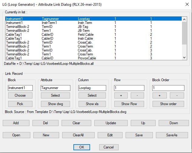
Good catch pkenewell , probably simpler to implement too. Done something simular in the past.... wow , 2015, has it been five years ago already... how time flies... don't even know how this program works anymore haha
1 point
-
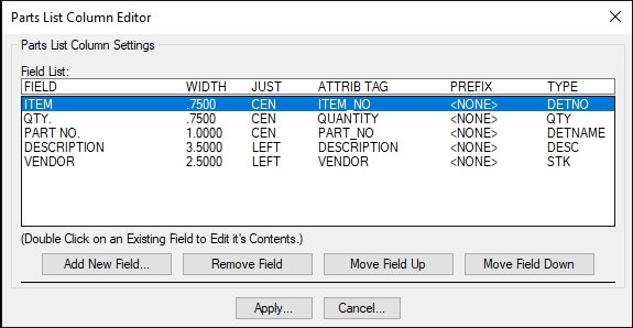
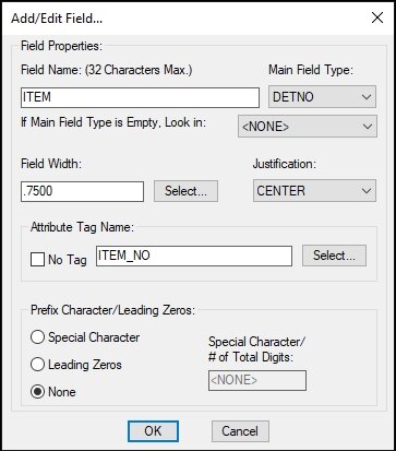
Another Idea is to have a List Box with all the values tabbed, then double-click to edit and display a nested dialog to edit the values. Attached is an example I use for a Parts List program I created a long time ago.
1 point