Leaderboard


Popular Content
Showing content with the highest reputation on 02/27/2024 in all areas
-
I believe any command that is built-in to AutoCAD is proprietary product and cannot be disclosed to the public. However, some built-in AutoLISP commands, for example, the Express Tools of AutoCAD, are all saved in your local computer and can be viewed anytime under your directory "C:\Program Files\Autodesk\AutoCAD 2021\Express" (assuming your CAD version is 2021). Anyways, that aside, just as the previous comment suggested, finding a point that overlaps with basically any curve is relatively easy. But finding the overlaps of two curves, even between two polylines as shown below, is not easy.
 1 point
 -
Using a delete window it does not matter what space your in, but if the objects are not in the same place in say multiple dwg's it will not work.1 point
-
Or if you need it to be something other than 45 degrees: (polar '(0 0 0) (cvunit <your_angle_in_degrees> "degrees" "radians") 10)1 point
-
A strategy that helps me debug is including trace statements. When you're not sure what a variable's value is, or even if you think you know, include a princ statement to print it out. Example: I have a real number variable named rando, so here's the trace statement: (princ (strcat "rando=" (rtos rando)) ":") I include the colon in case there's another trace statement after this one. You can always comment out these statements. In your case, you may want to print the values of blockPt and textPt to see what's happening.1 point
-
OK I think for me this is just to adjust the limits of what it thinks are part of the same arc1 point
-
This only assumes the horizontal and vertical lines are drawn in UCS, and not WCS: (defun c:vmirror nil (OnePointMirror '(00 10 00))) (defun c:hmirror nil (OnePointMirror '(10 00 00))) (defun OnePointMirror (dir / ss pt) (and (setq ss (ssget "_:L")) (setq pt (getpoint "\nSpecify base point <exit>: ")) (command "_mirror" ss "" "_non" pt "_non" (mapcar '+ dir pt) "No") ;; <--- Change to Yes to delete source object, or \\ to prompt user. (while (not (zerop (getvar "cmdactive"))) (command "")) ) (princ) ) And while this may be off the OP, this might be worth looking at as well: Quick Mirror.1 point
-
Are there some you do not want to enable linetype generation? For all Plines in a drawing, just Qselect>Polyline>Linetype generation>= Equals>No>OK, then go to properties and scroll down to Miscellaneous>Linetype Generation>Enabled. Are you looking for something to put them on the layers and linestyles as well? Maybe post a .dwg and specific instructions.1 point
-
Hi Friends, Greetings of the day! Can any one guide me how to develop the Fabrication drawings for Duct works using Revit, We are working on an US project, the client is expecting the Sheet Fabrication Drawings for the duct system. If any one have some sample drawings for the same, please share for the reference. Till now we have worked only developing the layouts. Thanks in advance for the support Ramana1 point
-
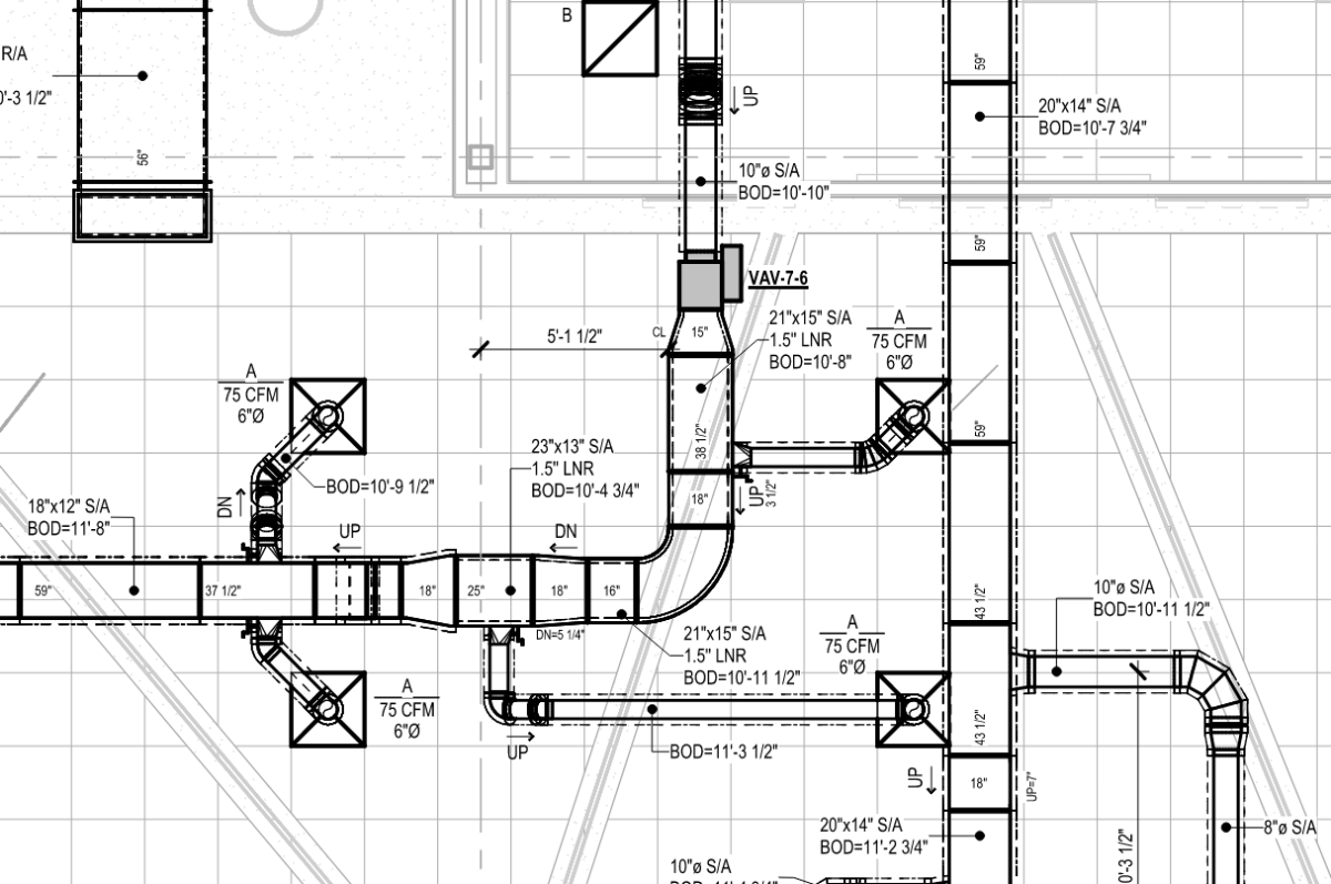
Are you using Autodesk Fabrication within Revit? And if so have you set up the fabrication database to meet the spec of the duct contractor's sheet metal shop with their duct tables? For true fabrication level detailing this would be a bare minimum requirement for takeoff purposes. Native Revit Families for the duct systems doesn't have things like duct joints or TDC/DM flanges, etc so it's hard to create true sheet metal fabrication drawings for a duct manufacturer to do a takeoff from. You'll need to consider using Fabrication within Revit. Also, the area of sheet metal fabrication drawings requires some added knowledge in SMACNA standards for things like offsets, transitions, duct joint lengths, material types and many other things. The way you're asking your questions leads me to believe you have very little experience in this and that may be something to consider with your customer in the US. The attached screenshot is from a project of ours that shows what FabParts in Revit looks like on a shop drawing deliverable for a sheet metal fabricator. Lots of information is needed and knowledge of the duct manufacturer's specs is a must.
1 point
-
Try setting Osnapz=0 (or maybe 1, read about it in Help).1 point
-
This will include a prompt for offset distance - I can't work out the dimension associativity though... I've set the DIMASSOC to 2, and even when I have finished the LISP and try to dimension myself manually, the dims are associative, so not sure whats going on here... (defun c:dimobj (/ ss off vlst ovar obj minpt maxpt crds) (if (and (setq ss (ssget)) (not (initget 7)) (setq off (getdist "\nSpecify Offset Distance: "))) (progn (setq vlst '("CMDECHO" "OSMODE" "DIMASSOC") ovar (mapcar 'getvar vlst)) (mapcar 'setvar vlst '(0 0 2)) (foreach obj (mapcar 'vlax-ename->vla-object (vl-remove-if 'listp (mapcar 'cadr (ssnamex ss)))) (vla-getboundingbox obj 'minpt 'maxpt) (setq crds (mapcar 'vlax-safearray->list (list minpt maxpt))) (command "_dimlinear" (car crds) (polar (car crds) (/ pi 2) (- (cadadr crds) (cadar crds))) (polar (car crds) pi off)) (command "_dimlinear" (car crds) (polar (car crds) 0 (- (caadr crds) (caar crds))) (polar (car crds) (/ (* 3 pi) 2) off))) (mapcar 'setvar vlst ovar)) (princ "\n<!> No Object Selected <!>")) (princ))1 point