Leaderboard


Popular Content
Showing content with the highest reputation on 12/12/2023 in all areas
-
Or this: (ssget "_X" '((0 . "HATCH") (2 . "~SOLID")))1 point
-
Think of it like this as you make each solid remember it (setq sol1 (entlast)) ie box, then when you use the subtract command you can use the entitiy names in the correct sequence. Have a go rather than us providing an answer. (command "extract" sol1 .......................)1 point
-
Is this a part of the dim styles settings? If so: (setvar "DIMBLK" ".") ;; "." ;;Arrow block name "." for closed flled else as properties (setvar "DIMBLK1" ".") ;; "." ;;First arrow block name "." for closed flled else as properties (setvar "DIMBLK2" ".") ;; "." ;;Second arrow block name "." for closed flled else as properties Something like that1 point
-
Except for the first line, my reply was a direct quote from the instructions provided by Penn-Foster. Each command is explained in the AutoCAD Help file. Note too that both myself and BIGAL have posted tree blocks that can be downloaded and used. The only way we could make it any easier for you would to be to do the project for you. Sorry... that ain't going to happen.1 point
-
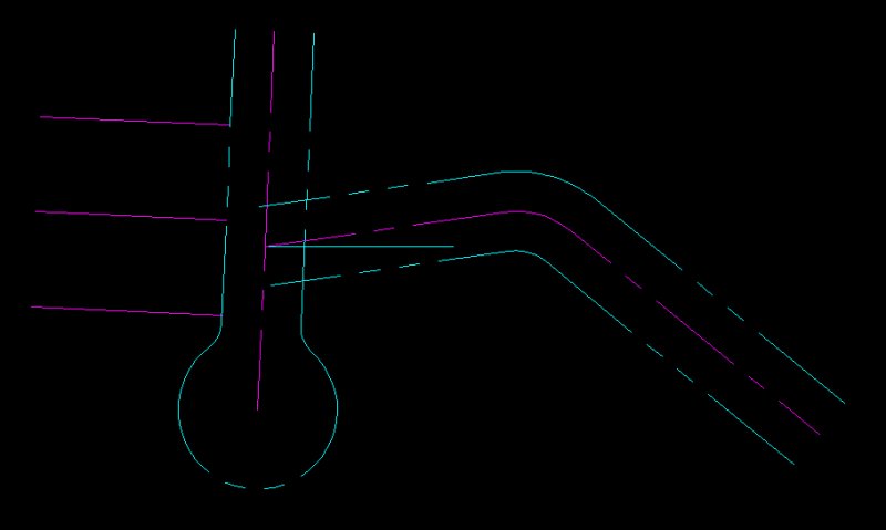
Before we move on to what is shown in the attached image let's stop. You previously created the centerline for SW Village Lane. Use the Fillet command with a 55 foot radius to add the curve. Stop. I'd like you to combine the line on either side of the curve with the curve itself so it is one complete entity. How do we do that? Easy...we use the Pedit command. Invoke the command and pick the west line. You'll be asked by AutoCAD if you want to make the line a polyline. Answer = yes. Now type 'J' (for Join) then pick the same line, the curve (arc) and the second line. AutoCAD will join all three lines together. Now offset the centerline 25 feet north and again 25 feet south. Your drawing should look like the above image.
 1 point