Leaderboard


Popular Content
Showing content with the highest reputation on 09/12/2023 in all areas
-
That is a hard shape to change, explode, fillet and erase comes to mind as 1st answer. Ok 2nd answer select pline segments in sequence, no arcs, then make a new pline from new line segments. So try this. Just pick segments press enter to stop picking it will close automatically. You must pick in order. (defun getplineseg (elst / elst ename pt param preparam postparam) (setq ename (car elst)) (setq pt (cadr elst)) (setq pt (vlax-curve-getClosestPointTo ename pt)) (print (setq param (vlax-curve-getParamAtPoint ename pt)) ) (print (setq preparam (fix param)) ) (print (setq postparam (1+ preparam)) ) (setq pt1 (vlax-curve-getPointAtParam ename preparam) pt2 (vlax-curve-getPointAtParam ename postparam)) ) (defun c:wow ( / oldsnap ent mp1 mp2 pt1 pt2 mpst) (setq oldsnap (getvar 'osmode)) (setvar 'osmode 0) (setvar 'filletrad 0.0) (setq ent (entsel "\nSelect pline segment: ")) (getplineseg ent) (command "pline" pt1 pt2 "") (setq mp1 (mapcar '* (mapcar '+ pt1 pt2) '(0.5 0.5))) (setq mpst mp1) (while (setq ent (entsel "\nSelect pline segment: ")) (getplineseg ent) (command "pline" pt1 pt2 "") (setq mp2 (mapcar '* (mapcar '+ pt1 pt2) '(0.5 0.5))) (command "fillet" mp1 mp2) (setq mp1 mp2) ) (setq obj (vlax-ename->vla-object (entlast))) (vlax-put obj 'Closed -1) (princ) )
 2 points
 -
Hi ziele_o2k, I am not a Civil engineer but this was an interesting problems with equally innovative solutions. Your idea of using a 'flat' pline to find parameters was also interesting. I an not aware of the methodology you use to measure speed and can't really interpret the speed test results. However, it was surprising to me that solution 1 was faster than solution 2. I was under impression that using AutoLISP functions is faster than creating (and deleting) geometry. Does this also mean using vlax-curve functions work slower than creating geometry? This needs to be verified. Here is my function (modified New_Approach) - It does away with creating / deleting temp geometry. - Uses simple Trigonometry instead of curve parameters. It does not use any vlax-curve (or any other vl-) functions. - No. of functions that are needed is reduced. I expect it to further reduce the time because of these factors. You can test to see if this is correct. By the way, this function works even when the road pline does not start at (0, 0). (You can try the function by moving the pline away from 0,0.) And it is possible to modify this function to include arc segments in the pline. Could require some efforts though, in adding and identifying the arcs. Hope you find it useful. (defun c:pLineY (/ ntLst road_start road_end division_distance kounter BasePt0 BasePt1 kounter pline_coordinates NewY NoOfVerices OverReach road_start_X road_end_X TotDst cur_x yPline ) ;;;;;;;;;;;---------------------- (defun get_pline_coordinates (enx) (if (setq enx (member (assoc 10 enx) enx)) (cons (cdr (assoc 10 enx)) (get_pline_coordinates (cdr enx)) ) ) ) ;;;;;;;;;;;;;;; ---------------- (defun getY () ;;;; Gets corresponding y on the pline (setq overReach nil) (while (and (> totDst (- (car basePt1) road_start_X)) (= overReach nil) ) (setq kounter (1+ kounter)) ;;; (if (= kounter (1- noOfVertices)) (setq overReach T) (setq basePt1 (nth (1+ kounter) pline_coordinates)) ) ;;;; ) ;;;;;;;;;;; (if (= overReach nil) (progn (setq basePt0 (nth kounter pline_coordinates)) ;;;;;;;; ;;;; y = (y2 - y1) / (x2 - x1) * (X -x1) + y1 (setq yPline (+ (* (/ (- (cadr basePt1) (cadr basePt0)) (- (car basePt1) (car basePt0)) ) (- cur_x (car basePt0)) ) (cadr basePt0) ) ) ) ) ;;;;;; ) ;;;;;;;;;;;; ------------------ ;;;;;; Execution starts here (setq pline_coordinates (get_pline_coordinates (entget (car (entsel "\nSelect pline: "))) ) ) ;;;;;;;;;;;; (setq road_start (nth 0 pline_coordinates) road_start_X (car road_start) res (list road_start_X) road_end (last pline_coordinates) road_end_X (car road_end) ) ;;;; ;;; (setq division_distance (getreal "\nDivision diatance: ")) (setq division_distance 50) (setq totDst division_distance) (setq cur_x (+ totDst road_start_X)) (if (< totDst (- road_end_X road_start_X)) ;;;; If dst > width of line exit (progn ;;;;;;;;; (setq kounter 0) (setq noOfVertices (length pline_coordinates)) (while (< kounter (1- noOfVertices)) (setq basePt0 (nth kounter pline_coordinates)) (setq basePt1 (nth (1+ kounter) pline_coordinates)) (setq newY (gety)) (if newY (setq res (cons newY res)) ) (if (< kounter (1- noOfVertices)) (setq kounter (1+ kounter) totDst (+ division_distance totDst) cur_x (+ division_distance cur_x) ) ) ) ) ) ;;;;; (reverse res) )1 point
-
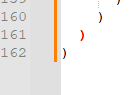
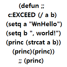
Extra bracket at end remove the red one is correct end for defun, use Notepad++ has checking built in.
1 point
-
I'll often prefix a variable with something, perhaps in this case something like Arr_ (for example Arr_Angle) just to be sure that it can never be confused with a function and still retain some sort of description just to avoid this1 point
-
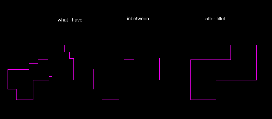
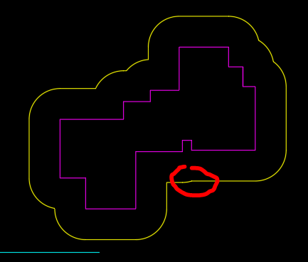
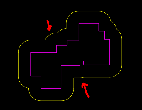
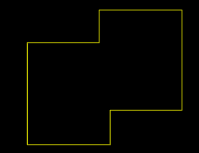
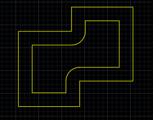
Here's an approach that might have some potential although there are a few coding challenges. Using offset, create an offset shape 1.5 mm outside the original shape. Delete all the fillets and replace them with chamfers. Note that if a fillet arc is not between a vertical and horizontal line then both the arc and the line "inside" should be deleted. Chamfer the resulting lines. Now construct an offset curve of 1.5 inside this shape. Replace the arcs with fillets and you have the desired end product! The most challenging coding part of this approach is determining which line segments should be deleted after the initial offset shape (i.e., the inside lines).
1 point
-
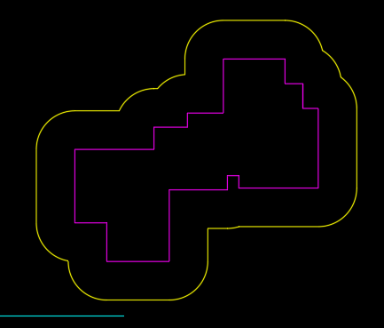
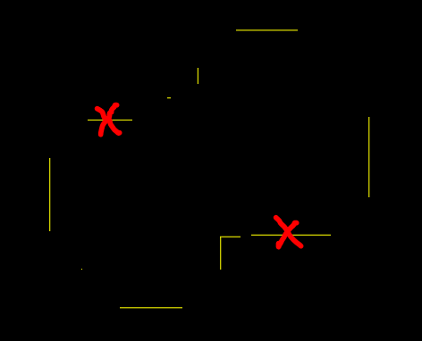
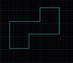
Before writing a routine, you must check that the conditions are logically flawless. From the length between polyline nodes, we need to distinguish between lines to be taken and lines not to be taken. Once the loop is run once, these two white lines in the example must survive. Since the rule is not grid snap 1.5 because the result's nodes do not fall to 1.5, deleting the right line must be done by looping once more with the result of the first loop. The left white line will survive though. Since the general routine makes judgments by comparing the front and back points, a new routine may be needed to estimate the edges using extension lines at the nodes at both ends. Extract the coordinates of each point of the polyline, first extract the cases where both sides are 1.5 or more from the length of the line segment (points marked with a 1.5 radius circle), and then draw only one side. After marking the point (marked by x) that is greater than 1.5, then draw a line first when there are continuous circles, draw directly towards the next point x on the circle. Now, we need to find the included angle in all coordinates other than 0 90 180 270 and remove that node. You also need to decide which side of the line to align it with. This is the guessing based on only the nodes, but if there is a condition that the area should not be modified in a way that makes it smaller, your example can be valid. In this case, you must add a routine to determine the area of the closed area and a routine to determine whether a point is inside or outside the closed polyline. It will become more complicated than guessing based on just the nodes.1 point