Leaderboard


Popular Content
Showing content with the highest reputation on 09/11/2023 in all areas
-
Because the tblobjname function returns an AcDbBlockBegin object for the Block Symbol Table so as to facilitate iterating over the block components (until an AcDbBlockEnd object is encountered); the AcDbBlockBegin class is derived from the AcDbEntity class, hence the equivalent ActiveX interface object is an IAcadEntity object. You can also observe this through the DXF data for the entities - tblobjname will return a BLOCK entity of class AcDbBlockBegin which is derived from the AcDbEntity base class: ( (-1 . <Entity name: 20458ff8900>) (0 . "BLOCK") (330 . <Entity name: 20458ff88a0>) (5 . "3C0") (100 . "AcDbEntity") (67 . 0) (8 . "0") (100 . "AcDbBlockBegin") (70 . 0) (10 0.0 0.0 0.0) (-2 . <Entity name: 20458ff88b0>) (2 . "test") (1 . "") ) The parent entity is a BLOCK_RECORD entity of class AcDbBlockTableRecord which is derived from the AcDbSymbolTableRecord base class: ( (-1 . <Entity name: 20458ff88a0>) (0 . "BLOCK_RECORD") (5 . "3BA") (102 . "{ACAD_XDICTIONARY") (360 . <Entity name: 20458ff88e0>) (102 . "}") (330 . <Entity name: 20458fef810>) (100 . "AcDbSymbolTableRecord") (100 . "AcDbBlockTableRecord") (2 . "test") (360 . <Entity name: 20458ff8900>) (340 . <Entity name: 0>) (102 . "{BLKREFS") (331 . <Entity name: 20458ff8920>) (102 . "}") (70 . 4) (280 . 1) (281 . 0) )2 points
-
Because of problems with the entmake and using trans have you thought about just go back to Command Pline. It works in current UCS. A couple of examples of insulation drawn in a UCS matching white line. A arc is supported in a pline sequence. Part of insul code. ; now put pts 3,4,5,6 (command "arc" "ce" p3 "arc" "-180" "l" p5 "arc" "ce" p6 p7 "l" p8)
 1 point
 -
A start with this ? (defun c:foo ( / ss ename nw_str) (vl-load-com) (setq ss (ssget '((0 . "INSERT") (66 . 1)))) (cond (ss (repeat (setq n (sslength ss)) (setq ename (vlax-ename->vla-object (ssname ss (setq n (1- n))))) (mapcar '(lambda (att) (setq nw_str (rtos (/ (atof (vlax-get att 'TextString)) (cvunit 1 "meter" "feet")))) (if (/= nw_str "") (vlax-put att 'TextString nw_str) ) ) (vlax-invoke ename 'GetAttributes) ) ) ) ) (prin1) )1 point
-
You can't have a variable share a named with a function. switch the angle variable to ang or something else. didn't really look at the rest of the code. would also suggest to shorten the some of the variable naming down.1 point
-
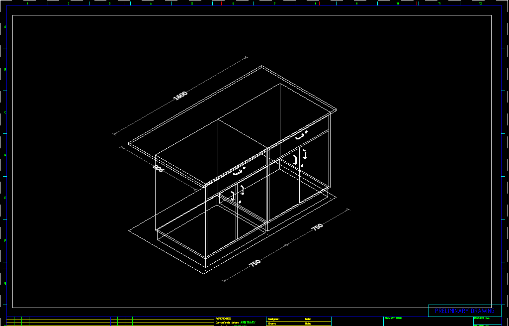
This is just a start to prove concept lots more to do. Based on supplied dwg. Ok for it to work rename Ph01 to Ph00, unlock viewport, delete all existing layouts as we are going to make new ones. UCS W PLAN so model space is in world Load code it should auto run. Just zoom in and pick a central point on your cabinets, each time you pick it will make a layout with a fixed for moment view angle. next version has choices. Keep picking a point inside objects new layouts will be made. Yes lots of stuff to still do. I made like 10 layouts as fast as I could pick a point. Need to think about scale factor so looks as a fit in viewport. (defun wow ( ) (setvar 'ctab "Model") (setq x (- (getint "\Enter start number "))) (while (setq pt (getpoint "\nSelect a point Enter to exit")) (setq tabn (strcat "Ph" (rtos (setq x (1+ x)) 2 0))) (command "layout" "c" "Ph00" tabn) (setvar 'ctab tabn) (command "mspace" "vpoint" "-1,-1,1") (command "zoom" "c" pt 2000) (setvar 'ctab "Model") ) ) (wow)
1 point
-
Ok starting to unravel the request the dwg put me off for a little while, so went back to basics, UCS W PLAN this shows the 3dobjects in plan view, should be able to just pick approx centre of objects, then make a layout, using the point and vpoint, can set the objects to centre of viewport. Need the set scale of viewport based on a 3d view say fill viewport then scale say 0.9 as a nice fit. Yes can get the outer box of the objects, thanks to Lee-mac. There are 4 view directions that is actually the easy part. Vpoint -1,-1,1 gives 3d front view. need to think more have something similar for houses.
1 point
-
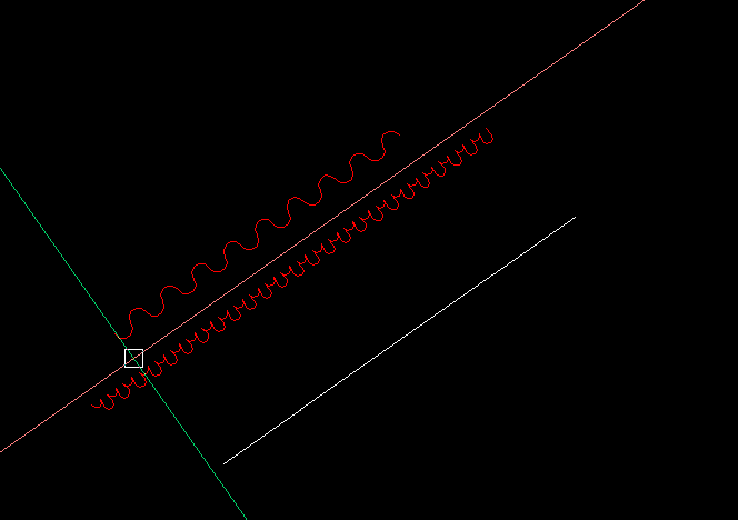
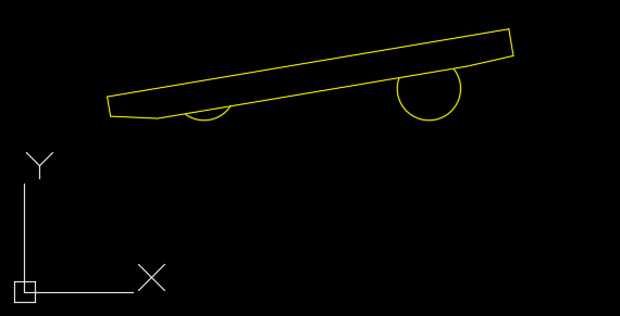
caralign_v11_lrm.dwgHere's an approach that will work if the curve is a spline. The program assumes that the two points of a block that will be required to lie on the spline are the block's base point and a point a known distance (L) on the x axis of the block. The program sets the base point on the spline and then determines then determines the location of the second point on the spline via numerical methods, i.e., it make a series of guesses. The first guess is a distance L along the spline. To use a spline in the sample file caralign_v11.dwg I modified the block named "auto" such that the radius of the two arcs are the same (0.35). The modified block is named "auto-2". Auto-2 The distance between the centers of the arcs was not modified. It is 2.4846. I then created a spline that closely represented the polyline path. The green curve in the image below is that spline. An offset spline (red) is created 0.35 from the "path" spline. The program ArraySpline is then used with a distance of 2.4846. The user may specify the distance between each block instance. In the example below I used 3. The offset curve is used as the path to guarantee that the arcs will be tangent to the original spline. The program could be easily modified to place a block at a specified location on a spline. (defun C:ArraySpline (/ L A blockname path pt smax smax dmax sL more p ang sp dpt ) ; Adds a series of blocks along a spline. The block's origin is placed on the spline. ; The angle of the block is determined by a second point of the block a distance L in the X ; direction of the block. The block's have a user defined spacing of A. ; L. Minardi 8/9/2023 (command "ucs" "w") (setvar 'osmode 0) (setq L (getreal "\nEnter distance between the block's base point and a point on the block's x axis: " ) A (getreal "\nEnter distance to next block: ") blockname (getstring "\nEnter block name: ") ) ;(setq L 1.3 A 1 blockname "block1") ; used for debugging (setq path (car (entsel "\nSelect Path.")) pt (vlax-curve-getStartPoint path) smax (vlax-curve-getEndParam path) dmax (vlax-curve-getDistAtParam path smax) sL (vlax-curve-getParamAtDist path L) more T ; flag for loop ) (while more ; loop for adding blocks until end of spline is reached (setq p (SplinePtAtDist path pt L) ; location on spline for block's second point ang (/ (* (angle pt p) 180.) pi) ) (command "-insert" blockname pt 1 1 ang) (setq dp (vlax-curve-getDistAtPoint path p) ; distance to p sp (vlax-curve-getParamAtPoint path p) ; parameter at p pt (vlax-curve-getPointAtDist path (+ dp A)) ; next block location p (vlax-curve-getPointAtDist path (+ dp A L)) ; initial guess for second point on spline dpt (vlax-curve-getDistAtPoint path pt) ; distance along spline to pt ) (if (< (- sMax sp) sL) ; test if another block will fit on spline (setq more nil) ) ) ; end while (princ) ) (defun SplinePtAtDist (path pt L / disPt p s spt sDelta i sgn err) ; find the point on a spline that is a distance L from the point pt, ; path - spline object name ; pt - known point on the spline that is closer to the beinning of the spline ; than the desired point p that is a straingt line distance L away. ; L - distance between the block's base point and a point on its x axis. (setq disPt (vlax-curve-getDistAtPoint path pt) p (vlax-curve-getPointAtDist path (+ disPt L)) s (vlax-curve-getParamAtPoint path p) spt (vlax-curve-getParamAtPoint path pt) sDelta (/ (- s spt) 3) i 0 sgn 1 ) (while (< i 20) ; sets maximum interations for solution (if (> L (distance pt p)) (progn ; true, L > distance (if (> (* sgn -1) 0) (setq sgn (* sgn -1) ; reverse search diection sDelta (/ sDelta 2); halve the interval search size ) ) ) (progn ; false L not > distance (if (< (* sgn -1) 0) (setq sgn (* sgn -1) sDelta (/ sDelta 2) ) ) ) ) (setq s (+ s (* sgn sDelta)) p (vlax-curve-getPointAtParam path s) ) ;;;(command "point" p) ; used for debugging (setq i (+ i 1)) (setq err (/ (abs (- (distance pt p) L)) L)) (if (< err 0.001) (setq i 100)) ; exit loop if error acceptable ) ; end while (setq p p) ) ; end defun
1 point
-
following this...will need this in the future1 point
-
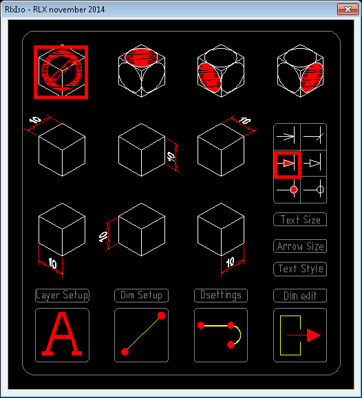
In responce to econeo from entmake donut thread You wanted to see my isometric dimensioning program , well than , here it is. I saw my colleages using ccp (cut copy paste) their dimensions so i decided to give them a hand (no not in that way you dirty ...) And just for the fun of it I wanted to be able to draw and use my own interface. Thats why I made a drawing , took a slide from that drawing and used that for my user interface. Not unlike the age of the digitizers. Be aware that all the dimensioning settings and textheight etc are hard coded because I wrote it specifically for my colleages here at Sabic. And we work in millimeters rather than inches. Hope you like gr. Rlx RlxIso.DCL RlxIso.LSP RlxIso.dwg RlxIso.sld
1 point