Leaderboard


Popular Content
Showing content with the highest reputation on 08/22/2022 in all areas
-
Also check under your mouse if their is lint or something moving around interfering with the laser. My coworkers like to put tape on the mouse for April fools.2 points
-
If I am overwriting text files I will often delete them first, however if the routine crashes in between the delete and create it all goes wrong.... Keep the delete and create close to each other in the progam Modifying your idea above, split the saveas part from the get file name part, then test the filename if it exists, something like this (setq MyFileName (getfiled "Saveas:" (strcat (getvar 'dwgprefix) "FileName") "dwg" 1)) (if (findfile (strcat MyFileNAme ".dwg")) (progn ;filename exsits (command "_.save" filename "_y") (princ (strcat MyFileName " was over written")) ) ; end progn (progn ; Filename doesn't exist (command "_.save" filename) (princ "A new file was created.") ;;does not replace the existing file ) ; end progn )1 point
-
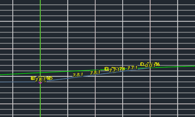
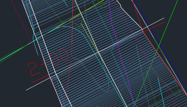
You may never see this issue, but just in case, this is how I solved it. In designing subdivisions, we sometimes create a swale to channel stormwater through an area where it might ordinarily collect or cause erosion. A swale is like a ditch but with gently sloping sides. Local jurisdictions like to have cross sections of how these swales were constructed. Until recently, we drew these cross sections by hand. The process is tedious and prone to error. I thought, why not use an alignment and the surveyor's as-built contours to create a corridor? That way we can generate cross sections automatically. Well, here's how one of the cross sections turned out: There should be one line representing the right-side bank with one grade label. Instead there are several. The obvious place to look is the corridor itself. Here it is at that cross section: The grey lines are the links that make up the corridor itself. The red line (labeled with station 2+00) is where the section cuts through. The white line is one of three links that intersect the cross section at the alignment. The problem, I assume, is that all of those links show up in the cross section because they're so close to the sample line. But I want only one line. What's causing the problem is a bend in the alignment. There's a vertex that coincides with the sample line (where the red line and the white line intersect in the second image). There are multiple links that cross the alignment in a small area, and they're at multiple angles. After some trial and error, I found a solution. The location of the swale is approximate, so you can't do this with a road (and this problem wouldn't happen on a road anyway). You add a curve to the alignment, in effect filleting the two line segments that form the angle. Even a one-foot radius is enough. That seems to force Civil 3D to use one link at the sample line, while the curve keeps the adjacent links far enough away that they don't show up in the cross section. A simpler solution is just to drag the alignment vertex away from the sample line. That doesn't eliminate the clutter but does move it off your cross section.
 1 point
 -
I made lakes, bridges, roads as a mega surface model had like 15 surfaces building each up to final surface, this was for 2km by 2km lot, the base surface was a sine wave 2km wide, with 150 m waves so not sure why you struggled, when you have this type of problem keep adding a new corridor creating a new surface that is based on the one prior think of daisy chain.keep cutting the last created surface.1 point
-
You can change the background color so maybe a light grey would be better for me black. Look at CONFIG screen Color’s are there.1 point
-
Nice one, I tried like you said and it works. Thanks for your suggestion and thinking.1 point
-
Note that the sides of the groove are not exactly parallel. One side has a slope of 2/3 while the other is 0.673... (35/52) Rather than using a box to subtract create a closed polygon using the noted dimensions, extrude then subtract.1 point
-
Why not just (startapp batchfile)1 point
-
Draw a cube, Draw lines on the edges so that snaps work at the right points, Cut all corners with the _slice command, specifying a section plane at three points, Where the cut planes cut off unnecessary parts, you need to set the _both option to save the cuted pieces, Glue the cut pieces back where the extra cuts are (_union command), Rotate USC with the Z axis along the groove that is drawn on the top face, Draw a box along the groove with a margin in length, Subtract this box from the main solid (_subtruct). That is, the idea is that everything that can be cut off is cut off by the Slice command. And we make all the recesses by subtracting other solids.1 point
-
Options>Display>Window Elements> Colors>2D model space>Viewport control>Color1 point