Leaderboard


Popular Content
Showing content with the highest reputation on 08/19/2022 in all areas
-
My forth grade math teacher always said that. Brings me a smile.2 points
-
I have generally found that Ordnance Survey uses metres as the drawing unit. So by checking the scale bar at the bottom of the picture, the units ARE metres. Confusingly, although working in metric units, the linetypes and hatch patterns are imperial sized! (system variable MEASUREMENT is 0) If you want to keep absolute coordinates, you must scale about 0,0 by 1000. If you are not too worried about coordinates, then scale 1000 times about any point in the drawing. Do set the length units precision to 0, otherwise you will be overwhelmed by the number of digits in the coordinates!2 points
-
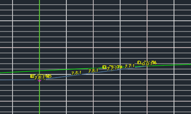
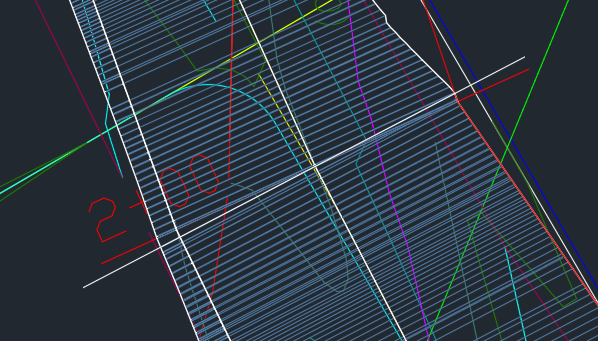
You may never see this issue, but just in case, this is how I solved it. In designing subdivisions, we sometimes create a swale to channel stormwater through an area where it might ordinarily collect or cause erosion. A swale is like a ditch but with gently sloping sides. Local jurisdictions like to have cross sections of how these swales were constructed. Until recently, we drew these cross sections by hand. The process is tedious and prone to error. I thought, why not use an alignment and the surveyor's as-built contours to create a corridor? That way we can generate cross sections automatically. Well, here's how one of the cross sections turned out: There should be one line representing the right-side bank with one grade label. Instead there are several. The obvious place to look is the corridor itself. Here it is at that cross section: The grey lines are the links that make up the corridor itself. The red line (labeled with station 2+00) is where the section cuts through. The white line is one of three links that intersect the cross section at the alignment. The problem, I assume, is that all of those links show up in the cross section because they're so close to the sample line. But I want only one line. What's causing the problem is a bend in the alignment. There's a vertex that coincides with the sample line (where the red line and the white line intersect in the second image). There are multiple links that cross the alignment in a small area, and they're at multiple angles. After some trial and error, I found a solution. The location of the swale is approximate, so you can't do this with a road (and this problem wouldn't happen on a road anyway). You add a curve to the alignment, in effect filleting the two line segments that form the angle. Even a one-foot radius is enough. That seems to force Civil 3D to use one link at the sample line, while the curve keeps the adjacent links far enough away that they don't show up in the cross section. A simpler solution is just to drag the alignment vertex away from the sample line. That doesn't eliminate the clutter but does move it off your cross section.
 1 point
 -
I use the .xyz shortcuts (defun c:MX () (ssget ":LI") (SAA_CMDACTIVE nil) (command "MOVE" "P" "" pause ".yz" "non" "@") (princ)) (defun c:MY () (ssget ":LI") (SAA_CMDACTIVE nil) (command "MOVE" "P" "" pause ".xz" "non" "@") (princ)) (defun c:MZ () (ssget ":LI") (SAA_CMDACTIVE nil) (command "MOVE" "P" "" pause ".xy" "non" "@") (princ)) ;;;========================================================== ;;; Continue pausing until exited command mode ;;; nil = pause ;;; otherwise pass string to use ;;; credit unknown ;;; usage example: (command "line" (SAA_CMDACTIVE nil)) ;;;========================================================== (defun SAA_CMDACTIVE ( passcmd / ) (if (null passcmd) (setq passcmd pause)) (while (not (= 0 (getvar "cmdactive"))) (if (= 'LIST (type passcmd)) (foreach x passcmd (command x) ) ;_foreach (command passcmd) ) ;_if ) ;end while )1 point
-
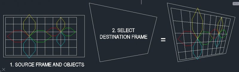
Hi, this lisp is working in 2D only: it generate a perspective view from a selected 2D plan or elevation. 1. Command: P2D 2. Select the source frame (trapezoid polyline) of the plan or elevation 3. Select drawing objects in that source plan or elevation 4. Select destination frame >>> a new perspective drawing would be draw arcordingly (see image and example drawing) 5. Repeat step 4 until you select none It is working only with straight lines, straight polylines and points. Pretty useful when you want to take a leap up from your 2D, for but donot have time to create a 3D model. New version on Apps Exchange Store, extrusion enabled P2D EXAMPLE.dwg P2D command.LSP
1 point
-
Let's work out what is happening for you then.. what does CAD tell you when you load and try to run this, are there any error messages given? (In AutoCAD these wil often be in the command line), let us have a clue...1 point
-
This is a more detail explain of how it works: http://www.yourspreadsheets.co.uk/your2dperspective---how-it-works.html Thanks1 point