Leaderboard


Popular Content
Showing content with the highest reputation on 05/20/2022 in all areas
-
If you just want to put something in text or mtext, case1. your text is object (vla-put-textstring your_text_obj your_text_string) case2. your text is ename (vla-put-textstring (vlax-ename->vla-object your_text_ename) your_text_string) The link is the code I recently used vla-put-textstring. This is the code to paste the text copied to the clipboard into the existed text in drawing. maybe this code has little relevance, but there is how to put something in the text2 points
-
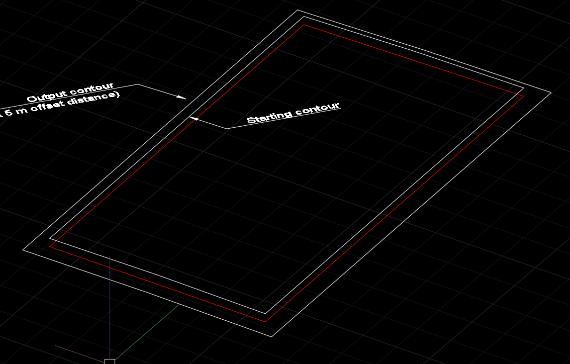
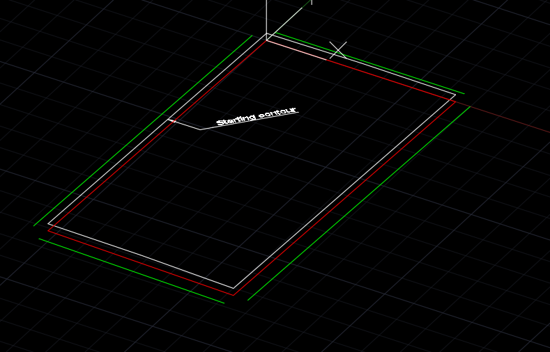
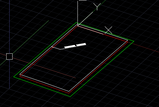
The following process is tedious but will yield the desired result (I think). Working on a new layer create 4 lines snapping to the vertices of the 3dpoly. Move the 4 lines in Z by - 2.5 ( 50% x 5m offset distance). Select one of the lines and use UCS OB to set a ucs for the line. Use Offset with a distance of 5. Repeat steps 3, 4, and 5 for the other edge lines. This will yield the lines shown in green below. Use chamfer to complete the 3D offset.
 2 points
 -
And easy midpoint of two points add them up and divide x y and z by 2 (setq mpt (mapcar '/ (mapcar '+ pt1 pt2) '(2 2 2)))1 point
-
@Steven P You can also subtract the X's and the Y's to get W and H. (and (setq p1 (getpoint)) (setq p2 (getcorner p1)) (setq r (mapcar 'abs (mapcar '- p1 p2))) (mapcar 'print r) )1 point
-
Love it when a small hint sets you on your way again, if you need anything more just shout out.1 point
-
Some times i tend to over think things playing devil's advocate here asking a stupid question. But why are you comparing it against another string that exists in a variable and not just overwrite it with the variable string cutting out the middle man? like exceed said a example drawing or code would help narrow down what you want to do.1 point
-
I can't be sure if I understand correctly because there is no example code or drawing, Selecting text from the entire drawing without user selection (ssget "X" '((0 . "*TEXT))) ends with this one line. Changing text is sometimes convenient with (vl-string-translate ~~) To execute a command without a dialog box, add - in front of the command.1 point
-
If you have selected Big Ol String then that should be accessible to replace later as an entity After that you might look at ent update to replace the text with its new text. Should be that you update dxf code '1' How big is the Big Ol String by the way? If it is very big ol string or massive ol string you might find that the text is split between a couple of dxf codes, you'll have to delete these before you put your new text into dxf 1. If I get chance I have this somewhere and can dig it out later, and if not might give you a clue where to look1 point
-
Wow this works. thank u very much. saves lot of time.1 point
-
OK So it you might have made something like this if you got it to work: (defun c:testthis ( / spt1 spt2 roomname a b c d scpt1 mywidth myheight) ;; after the '/' are local variable names (setq ;;setq: Tells LISP you are setting a variable spt1 (getpoint "\nPick the first point") ;;should be obvious what this does spt3 (getcorner "\nPick the next corner" spt1) ;;should be obvious what this does roomname (getstring "\nEnter Room Name: " T) ;;T allows spaces, else space acts as a return a (if (< (car spt1)(car spt3))(car spt1)(car spt3)) ;;Lower Left X coord car gives first item in a list, here x coord b (if (> (car spt1)(car spt3))(car spt1)(car spt3)) ;;Upper Right X coord c (if (< (cadr spt1)(cadr spt3))(cadr spt1)(cadr spt3)) ;;Lower Left y Coord cadr gives second item in a list, here y coord d (if (> (cadr spt1)(cadr spt3))(cadr spt1)(cadr spt3)) ;;Upper Right Y Coord ) (setq mywidth (abs (- a b))) ;;abs for absolute value (witohut = or -), (- is subtract (setq myheight (abs (- c d))) ;;center points (setq scpt1 (list (/ (+ a b) 2) (/ (+ c d) 2)) ) ;;create a coordinate which is a list (/ for divide (+ for add (command "mtext" scpt1 "J" "MC" scpt1 (strcat roomname "\n" (rtos mywidth 2 2) " x " (rtos myheight 2 2 )) "") ;;Command echos what you'd type in command line, anything in "" is a fixed value in else it is calculated ) Put a few notes in if you want to learn how it does what it does1 point
-
Research the topic "rendering architectural drawings".1 point
-
Yeah I saw that Steven but they way they have their layers named the list would show up as 1, 10 - 19, 2, 20 - 29, 3 Was thinking about that. if they need it to do something like that ill update the code. -edit- Also had vplayer to turn off all layers but it was late and took it out. that's why their is lst2str in there. converting ("01" "02 ..." to "01,02..." I guess you could add it back in before mspace. was misunderstanding what All meant in the options it means all viewports on the current tab not drawing. (vl-cmdf "_.vplayer" "f" (lst2str "," layer) "all" "" "")1 point
-
This works for the OP I think (not tested but I assume it does, unusual for you if it doesn't) For future and others looking at this I might be tempted to change the layer list to generate the list from what is in the drawing: https://forums.autodesk.com/t5/visual-lisp-autolisp-and-general/get-list-of-all-layers-in-lisp/td-p/822262 . OP can add more layers as they want without worrying about the code. You might need to create an exceptions list to remove layers from the list (perhaps with a wcmatch and a vl-remove-if combination). Another option would be if this list was just numbers 1, 2, 3, 4 etc. to create it using a repeat loop and rtos that value to go into the list Both these could have user input to say start at layer 5 and end at layer 14 for example But that is just me with not a lot to do on a Friday morning and thinking too much1 point
-
It was on my to do list mhupp but saved me, the 1st 22 layers need to be set to on for the layouts to make any sense, the 1-48 off, then do layouts 1-48 turning 1 only then 2 only then 3 only and so on, yes no 2 layer.1 point
-
Ok this kinda machine guns thought the layouts. Doesn't really have any error checking and is currently only limited by the number of layouts. I also renamed the layers 01 - 09 so they sort better. (missing 02) This works off of two list the layout tabs and the layers. go to the tab you want to start unfreezing layers and type the command it will then ask you what layer to start on. type 01 if you want to do 01-48. then it steps though each layout to the right thawing the next layer on the list using the vplayer command. See attached drawing. ;;----------------------------------------------------------------------------;; ;; Unfreeze one layer per layout (defun C:foo (/ layer lay lst tab) (setvar 'cmdecho 0) (setq layer '("01" "02" "03" "04" "05" "06" "07" "08" "09" "10" "11" "12" "13" "14" "15" "16" "17" "18" "19" "20" "21" "22" "23" "24" "25" "26" "27" "28" "29" "30" "31" "32" "33" "34" "35" "36" "37" "38" "39" "40" "41" "42" "43" "44" "45" "46" "47" "48") ) (setq lay (member (getstring "\nStart with Layer: ") layer)) (setq lst (member (getvar 'ctab) (layouts))) (foreach tab lst (setvar "ctab" (car lst)) (vl-cmdf "_.mspace") ;assumes one viewport per tab (vl-cmdf "_.vplayer" "T" (car lay) "" "" "") (setq lay (cdr lay)) (setq lst (cdr lst)) ) (setvar 'cmdecho 1) (princ) ) (defun Layouts (/ laylst tab lay id name) (setq laylst (massoc 350 (dictsearch (namedobjdict) "acad_layout"))) (foreach tab laylst (setq lay (entget tab)) (if (not (equal "Model" (setq Name (last (massoc 1 lay))))) (setq id (cdr (assoc 71 lay)) lst (cons (cons id name) lst) ) ) ) (setq lst (mapcar 'cdr (vl-sort lst '(lambda (x y) (< (car x) (car y)))))) ) (defun massoc (key alist / nlist) (foreach x alist (if (eq key (car x)) (setq nlist (cons (cdr x) nlist)) ) ) (reverse nlist) ) ;;----------------------------------------------------------------------------;; ;; Function to convert list to string ;; (lst2str "," lst) (defun lst2str (dlim lst / rtn) (vl-load-com) (setq rtn (car lst) lst (cdr lst)) (repeat (length lst) (setq rtn (strcat rtn dlim (car lst)) lst (cdr lst) ) ) rtn ) Q71319-15-REV3 QAUT - layers.dwg1 point
-
Thank you Steven. I think I saw this in a forum with you & @JuniorNogueira a while back when i was searching the web for something to achieve this. I will test this out but it looks like just brings the centre text coords of a rectangle?: I have 19 to 20 different blocks, in the example attached I have put most commonly used which is 5 blocks. I have scourged Lee Macs lisps, credit to @Lee Mac. The closest I could find was what does the exact opposite of what I am trying to achieve which is http://lee-mac.com/autoblockbreak.html Also another important thing to note that my blocks are dynamic blocks in the test dwg not standard blocks. I am abandoning the thought/requiring this to go to the geometric center as it might be too hard and extra steps. I am thinking the thought process of a program to achieve this is a program that scans for the (Insertion Point/Alignment Parameter circle) of a block instead, then scans for polylines snapped to the edge of the block then adds a vertex from the edge of each polyline where it is snapped to the block boundary, then snaps that to that Insertion point of the block. Maybe that's just me thinking too much of logic of this.
1 point
-
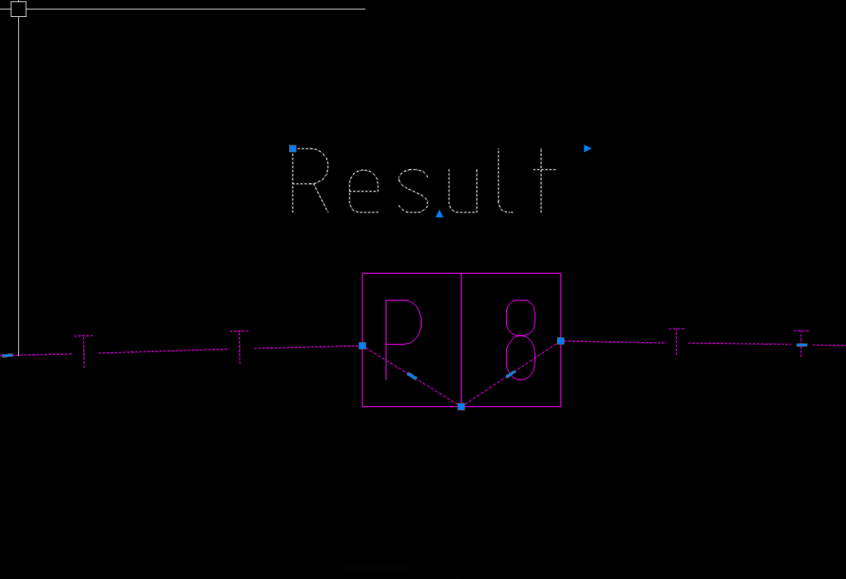
Since everything is on the same layer I splits up the polylines based on their color. then calculate a small area at the endpoints to see if anything magenta polylines are inside. totally useless if the polylines are any other color. (defun C:COUNT (/ ) (prompt (strcat "\nArrows at yellow Polylines: " (itoa (count 2)))) (prompt (strcat "\nArrows at red Polylines: " (itoa (count 1)))) (princ) ) (defun count (col / c ss ent lst pt1 pt2) (setq c 0) (if (setq ss (ssget "_X" (list '(0 . "*POLYLINE") (cons 62 col)))) (foreach ent (vl-remove-if 'listp (mapcar 'cadr (ssnamex ss))) (setq lst (vl-remove-if 'not (mapcar (function (lambda (p) (if (= 10 (car p)) (cdr p)))) (entget ent)))) (setq pt1 (mapcar '- (car lst) '(100 100))) (setq pt2 (mapcar '+ (car lst) '(100 100))) (if (ssget "_C" pt1 pt2 '((0 . "*POLYLINE") (62 . 6))) (setq c (+ c 1)) ) (setq pt1 (mapcar '- (last lst) '(100 100))) (setq pt2 (mapcar '+ (last lst) '(100 100))) (if (ssget "_C" pt1 pt2 '((0 . "*POLYLINE") (62 . 6))) (setq c (+ c 1)) ) ) ) c ) : COUNT Arrows at yellow Polylines: 6 Arrows at red Polylines: 31 point
-
Is that true?
1 point
-
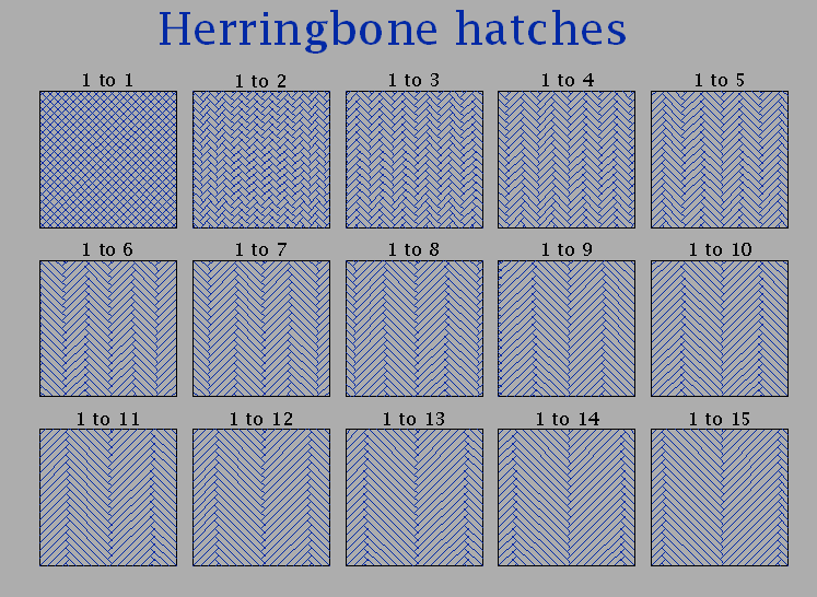
In Herringbone patterns, that consist of rectangles only, the length of the block is always the width of the block multiplied by an integer (whole number). It makes it easier to use to have a pattern at 45° with a unit width. This can be scaled to suit, i.e. a scale of 3 for 3" wide blocks, and a scale of 75 for 75mm wide blocks. It all depends on the ratio. So here is a general formula with no irrational numbers and with a couple of worked examples of pattern files, and a picture of the successive hatches (I do know that a 1 to 1 ratio is not conventional herringbone, but I put it in to complete the picture):- *HbR, Herringbone with width to length ratio 1 to R 45, 0,0, 1,1, (R+1),-(R-1) 135, 0,0, -1,1, R,-(R-1),1 *eldon May 2022 *Hb6, Herringbone with width to length ratio 1 to 6 45, 0,0, 1,1, 7,-5 135, 0,0, -1,1, 6,-5,1 *eldon May 2022 *Hb15, Herringbone with width to length ratio 1 to 15 45, 0,0, 1,1, 16,-14 135, 0,0, -1,1, 15,-14,1 *eldon May 2022
1 point
-
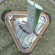
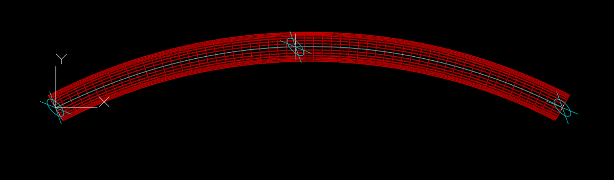
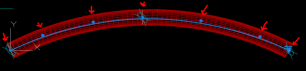
One issue not immediately apparent is that the two ends of the Revit geometry (Pipe) are cut at an angle not square to the prescribed arc. Hence, the inner and outer sections are elliptical, not circular. Using the sectional geometry near - but not at - the ends, circles could be recreated via 3PtUCS then 3PtCirc (Radii 5.40 and 5.03). An additional application of that procedure near the pipe’s midpoint gives three circles to work with. Like the above sequence, the three circle centers can be used with 3PtUCS then 3PtArc. A circle can be swept along that arc, and the two ends can be SolidEdit – Offset to extend beyond the Revit geometry, and 3Pt Slice can match the odd angles. 3DPipe_2016.dwg1 point
-
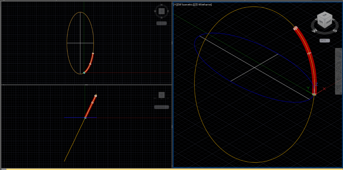
It appears that the tube lies on a plane so the first step is to create a UCS with an XY plane that passes through the center of the tube. I used three points located at the center of the tube at its ends and approximate midspan. I tried fitting an arc to the curve by finding the intersection of of the perpendicular bisectors for the lines connecting the end points to the midpoint but determined that the shape could not be approximated with an arc so decided to create a spline for the tube's centerline. I like creating splines using Control Vertices as it gives me better control. I started by creating a spline with 7 CVs making sure it started and ended at the precise end points of the tube. I wasn't too careful about the location of the other 5 CVs as I know they would be moved. It is important to keep in mind that the second CV and the next to the last CV control the tangent direction and radius of curvature of the spline at its beginning and end. Once I had the 7 CVs and with all object snaps off I moved the 2nd CV relative to the end making sure to keep the tangent vector correct but observing how the radius of curvature was changng as it met the tube's curvature. Once I was happy with the beginning and the end shape I moved on to moving CVs 3, 4 and 5. The results are not perfect but should be sufficient. It is best to use as few CVs as possible. Many people think more is better but more CVs (or fit points as well) can actually produce worse results as their is an increased likelihood of getting ripples in the curve when using too many defining point (CV or Fit).
1 point
-
@lido FYI in this case you can just concatenate the layer names with comma, like: (8 . "L1,L2") without the use of 'OR" logic operator.1 point