Leaderboard


Popular Content
Showing content with the highest reputation on 03/02/2022 in all areas
-
Ok as plot is set to fit selected out put size, you can control the pixel size of the jpg, a A1 24x36 will be in say Mb size, a A4 may be suitable, under Options Plot you can make your own jpg size. Try to use correct ratio check pc screen seetings.2 points
-
If I was checking this I would look at your (command "-insert" "Map_Survey_Point" x_y "" "" "" desc elev pntnum) line Perhaps print to screen everything it is saying - you have probably done this? and then you can see what it is doing a bit more clearly something like (princ "\n x_y: ") (princ x_y) (princ "\n desc: ") (princ desc) (princ "\n elev: ") (princ elev) (princ "\n pntnum: ") (princ pntnum) (princ "\n") Also might be worth a check that the block is loaded into the drawing file too - probably is of course, but as an error check (if (tblsearch "block" "Map_Survey_Point") (progn (princ "Yes - So Do Something") ) ;end progn (princ "Block doesn't exist in this drawing") ) ; end if I put this together just to check (defun c:testthis ( / ) (setq MyBlock "Map_Survey_Point") (setq lst (list 89 2.90716e+06 794227.0 45.04 BLDGCOR)) (setq pntnum (nth 0 lst) x (nth 1 lst) y (nth 2 lst) elev (nth 3 lst) desc (nth 4 lst) x_y (list x y) ) (princ "\n x_y: ") (princ x_y) (princ "\n desc: ") (princ desc) (princ "\n elev: ") (princ elev) (princ "\n pntnum: ") (princ pntnum) (if (tblsearch "block" MyBlock) (progn (command "-insert" MyBlock x_y "" "" "" desc elev pntnum) ) ;end progn (princ "Block doesn't exist in this drawing") ) ; end if ) The only thing it isn't checking is how you make lst.. and if it doesn't work then that is your problem1 point
-
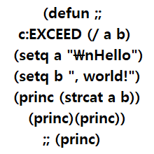
1. if you want just how to input wmf to excel. my routine makes .wmf image file in .dwg file's directory. just insert like png or jpeg same way. 2. if you want just image with fixed size. jpgout or pngout make same pixel size with your autocad drawing window. (not coordinates or size in drawing, just window box size you can see) so, this is Cheating way. I like cheating When specifying pt1 and pt2, you do not enter pixels. just picking coordinates. so, width of the output image value is entered height of the output image is automatically adjusted according to the xy ratio of pt1 and pt2. Because it is affected by the window size, it worked normally at a width of 1500 or less in an environment of 1920x1080. and, In my environment -16px is insufficient in width -55px is insufficient in height. it's probably because of the scrollbars and titles of the drawing window. You can test it in your own environment and change this number. (defun c:ss (/ ods pt1 pt2 patch nm ss acdoc input_width input_height x_dist_selection y_dist_selection xy_ratio _opendirectory) (setvar "cmdecho" 0) (setq ods (getvar "osmode")) (setvar "osmode" 0) (setq acdoc (vla-get-activedocument (vlax-get-acad-object))) ;edited line (setq pt1 (getpoint "\nSelect the first point:") pt2 (getcorner pt1 "\nselect the second point:" ) ph (strcat (getvar "dwgprefix") (vl-filename-base (getvar "dwgname")) ".png") ;edited line ) (setq x_dist_selection (abs (- (car pt1) (car pt2)) )) ;edited line (setq y_dist_selection (abs (- (cadr pt1) (cadr pt2)) )) ;edited line (setq xy_ratio (/ y_dist_selection x_dist_selection)) ;edited line (initget 7) ;edited line (setq input_width (getint "\nInput image width (under approx.1500 is best):")) (setq input_height (atoi (rtos (* input_width xy_ratio) 2 0)) ) ; if 1:1 scale, delete above 3 lines (initget 7)~(setq input_height ~) ; and add this (setq input_width x_dist_selection) (setq input_height y_dist_selection) (setq input_width (+ input_width 16)) ; 16 is my environment gap of window size & image size. shoud be edited (setq input_height (+ input_height 55)) ; 45 is my environment gap of window size & image size. shoud be edited ;(princ "\n xy_ratio - ") ;(princ xy_ratio) ;(princ "\n input_width - ") ;(princ input_width) ;(princ "\n input_height - ") ;(princ input_height) (if (setq ss (ssget "w" pt1 pt2)) ;'((0 . "lwpolyline,line,ARC")))) (progn (command "_Zoom" "OB" ss "") (vla-put-height acdoc input_height) ;edited line (vla-put-width acdoc input_width) ;edited line (command "_pngout" ph "all" "") ;edited line for all entities, replace with (command "_pngout" ph ss "") ) ) (command "_Zoom" "p") (vla-put-windowstate acdoc 3) ;edited line (command "_syswindows" "c") ;edited line (setvar "osmode" ods) (princ "\ndone.") (princ (strcat "\nimage output path:" ph)) (defun _opendirectory (path / sa) ;edited line (if (and (eq 'str (type path)) ;edited line (findfile (vl-string-right-trim "\\" path)) ;edited line (setq sa (vlax-create-object "Shell.Application")) ;edited line ) ;edited line (progn (vlax-invoke sa 'explore path) (vlax-release-object sa)) ;edited line ) ;edited line (princ) ;edited line ) ;edited line (_opendirectory (getvar 'dwgprefix)) ;edited line (setvar "osmode" ods) (princ) ) Because png has better quality than jpeg, I changed it at will1 point
-
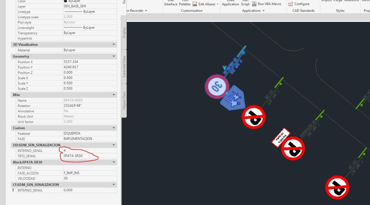
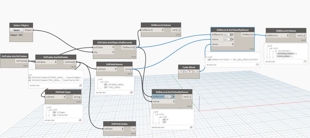
TRY LISP I notice to field type (defun c:AAaddid1 (/ n inc enam idd efn) (setq tn "SDM_SEN_SENALIZACION") (prompt "Seleccionar señales") (princ) (setq n (getint "\n Ingrese valor de Inicio: ") ss (ssget '((0 . "insert"))) ) (setq inc 0) (repeat (setq len (sslength ss)) (setq enam (ssname ss inc)) (setq idd (itoa n)) (setq efn(vla-get-effectivename(vlax-ename->vla-object enam))) (ade_odaddrecord enam tn) (ade_odsetfield enam tn "INTERNO_SENAL" 0 n) (ade_odsetfield enam tn "TIPO_SENAL" 0 efn) (command "chprop" enam "" "c" "ByLAyer" "") (setq inc (1+ inc) n (1+ n) ) ) (alert "The entities selected with INTERNO_SENAL were updated") (princ) )
 1 point
 -
1 point
-
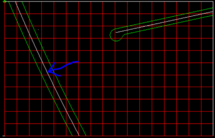
Cedar Park Drive is not a straight road. It is an arc segment, a relatively flat arc. The centerpoint of the arc is located outside of the bounds (grid) that is why it does not fall within the 850'x550' grid dimensions. You do have all the necessary information to construct the centerline of Cedar Park Drive and then the width of the road as well. See image below. The blue arrow points to the centerline of Cedar Park Drive.
1 point
-
I have only been half following this so apologies if I am wrong. When I tried JPGOUT wasn't clipping objects to an area but would include all the selected object - there might be a setting in there somewhere to just output the selected area, I don't know. Now he mentioned it, makes more sense to plot to jpg, and then you can select only the required area, loads of example out there how to do that I reckon, Reason I was commenting, can you use (startapp ... ) or something similar to start the windows snip and sketch tool via a LISP ? Had a quick look but not too long to see if it is possible, you could use the snipping tool with (startapp "SnippingTool.exe") for example. What are you going to be doing with the screenshot once you have it by the way, there might be other way to get the result you want1 point
-
Seems to output your Drawing Area and looking like you need to use @BIGAL method if you want to only output between pt1 and pt21 point
-
Hello, i want a macro that isolate a layer, then change all layer except layer in use to a color. Same thing for layuniso for reverse operation and recover the previosuly layer state.1 point