Leaderboard

Popular Content
Showing content with the highest reputation on 03/01/2022 in all areas
-
Ok as plot is set to fit selected out put size, you can control the pixel size of the jpg, a A1 24x36 will be in say Mb size, a A4 may be suitable, under Options Plot you can make your own jpg size. Try to use correct ratio check pc screen seetings.1 point
-
I would be uneasy on relying on visible effects to check whether a line is orthogonal. Set the angle precision to 6, and just click on each line in turn. The properties will show which lines are not perfectly horizontal or vertical. No zooming necessary!1 point
-
(defun c:addid1 (/ n inc enam idd efn) (setq tn "SDM_SEN_SENALIZACION") ;nombre de la tabla fijo. (prompt "Seleccionar señales") (princ) (setq n (getint "\n Ingrese valor de Inicio: ") ss (ssget '((0 . "insert"))) ) (setq inc 0) (repeat (setq len (sslength ss)) (setq enam (ssname ss inc)) (setq idd (itoa n)) (setq efn(vla-get-effectivename(vlax-ename->vla-object enam))) (ade_odaddrecord enam tn) (ade_odsetfield enam tn "INTERNO_SENAL" 0 idd) (ade_odsetfield enam tn "TIPO_SENAL" 0 efn) (command "chprop" enam "" "c" "ByLAyer" "") ;.... talvez no sea necesario...??? (setq inc (1+ inc) n (1+ n) ) ) (alert "Se actualizaron las entidades seleccionadas con INTERNO_SENAL") (princ) ) I am not sure what you mean. What is OD? And looking like "field" you means "attribute", in the language of AutoCAD? Or it is really "field"? For the information, above is the lisp ADD_ID.lsp, quite short so it can be easily pasted in the post. In the lisp, unknown functions are: (ade_odaddrecord ...) (ade_odsetfield ...)1 point
-
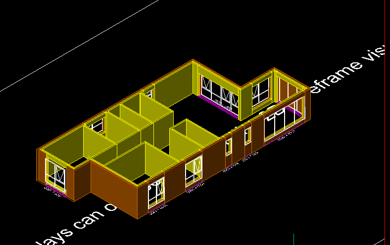
A 2.5d written around 1991 for Autocad old post though.
 1 point
 -
in 2D and 2.5D modelling you describe an object with points and lines. You "pretend" to show 2.5D objects in 3D via some "tricks" like perspective transformation and hidden line elimination. In a true 3D modelling you describe an object with surfaces, i.e., via the light the object reflects. For example you say that there is a sphere at position x,y,z with radius r and color (r,g,b), relative to a light source and your eye (or the camera) by calculating the "normal" vectors coming out from the sphere to your eye, where you "see" a shiny object with some shading and degredation in color. There are no lines or points (unless you explicitely want to draw one).1 point
-
Not sure how i came across this old thread but in the machining world 2.5d is typically a setup where you can make any movements you want in X and Y but you can only go up/down independent of the other axis in Z. So in CAD i would relate that to only being able to Extrude your 2d sketch. While it is 3d you really dont gain very much from it.1 point
-
I've always referred to 2.5 d as a simple wire frame drawing where you are unable to fully hide objects. Things that are drawn using the 3d coordinate system.1 point
-
Older releases of AutoCAD were derisively called 2.5D because their 3D capabilities were very limited. You could view 3D models but creating them was difficult due to the lack of 3D tools. AutoCAD LT might be considered 2.5D as you can view 3D but you can't do much to edit 3D.1 point
-
See if this helps 2.5D.1 point