Leaderboard


Popular Content
Showing content with the highest reputation on 12/26/2021 in all areas
-
Now this is spot on! thanks alot buddy!1 point
-
SEE (defun c:QQQnewleader ( / C EXYZ NEWLEADER PTEN PTS_SS SS_LEN ) (setq pts_ss (ssget (list (cons 0 "*TEXT")))) (setq ss_len (sslength pts_ss)) (setq c 0) (while (< c ss_len) (progn (setq pten (ssname pts_ss c)) (setq exyz (cdr (ASSOC 10 (ENTGET pten)))) (command "._MLEADER" exyz (list (+ 0.5 (car exyz)) (+ 0.2 (cadr exyz)) (caddr exyz)) "") (setq newleader (vlax-ename->vla-object (entlast))) (vla-put-textstring newleader (cdr (ASSOC 1 (ENTGET pten)))) (setq c (+ c 1)) ) ) (princ) )
 1 point
 -
see this is1 point
-
(setq exyz (cdr (ASSOC 10 (ENTGET(car (entsel "\nSelect" )))))) (setq exyz (vlax-get (vlax-ename->vla-object (car (entsel "\nSelect" ) )) 'insertionpoint) )1 point
-
hi try ;;https://forums.autodesk.com/t5/visual-lisp-autolisp-and-general/lisp-for-text-to-multileader/td-p/6264591 (defun c:am (/ newleader pt1 pt2 ss txt x w rjp-getbbwdth) (vl-load-com) (defun rjp-getbbwdth (obj / out ll ur) (vla-getboundingbox obj 'll 'ur) (setq out (mapcar 'vlax-safearray->list (list ll ur))) (distance (car out) (list (caadr out) (cadar out))) ) (if (setq ss (ssget '((0 . "*TEXT")))) (progn (setq txt (apply 'strcat (mapcar 'cdr (vl-sort (mapcar '(lambda (x) (cons (vlax-get x 'insertionpoint) (strcat (vlax-get x 'textstring) " ") ) ) (setq ss (mapcar 'vlax-ename->vla-object (vl-remove-if 'listp (mapcar 'cadr (ssnamex ss))) ) ) ) (function (lambda (y1 y2) (< (cadr (car y2)) (cadr (car y1)))) ) ) ) ) w (car (vl-sort (mapcar 'rjp-getbbwdth ss) '>)) txt (apply 'strcat (mapcar 'chr (reverse (cdr (reverse (vl-string->list txt))))) ) ) (mapcar 'vla-delete ss) ) ) (if (and (setq pt1 (getpoint "\nSpecify leader arrowhead location: ")) (setq pt2 (getpoint pt1 "\nSpecify landing location: ")) ) (progn (command "._MLEADER" pt1 pt2 "") (setq newleader (vlax-ename->vla-object (entlast))) (vla-put-textstring newleader txt) (vla-put-textwidth newleader w) ) ) (princ) )1 point
-
This is only relevant for 1 dim and needs to be changed for every new dim ObjId 1948505430096 also the .16.2 is not necessary. Hint (LM:objectid (vlax-ename->vla-object ent)) Lee-mac.com1 point
-
Again, I appreciate the delving into history, but this is a modern problem, and as such I would expect the solution to be contiguous lines satisfying all of the information provided. I think that the position of the 12 dimension is crucial. It is not wrong where it is, but it does not add to the solution. My solution incorporates all of the information. Your solution ignores some information, because you know better. I wonder if the tutor who set the original problem will honour us by providing the solution. One can but hope!!1 point
-
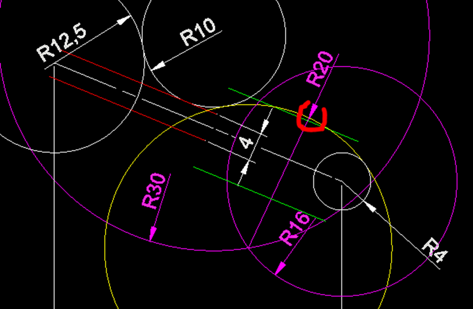
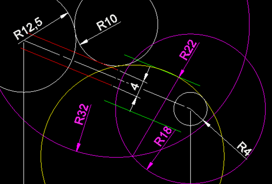
Another “old schooler” here. Let me take a different approach to this discussion and assume the roll of the designer of the part and it’s the 1960’s (pre-CAD). I set the WABAC (Wayback Machine) to 1965 and I’m a summer intern at American Can where I work on the design of parts for packaging systems. I’m working on a drafting board, pencil and erasing shield in hand, along with a brush to wipe away the residue from my multiple erasures. I’m at the stage of designing the handle. The 12.5 cylindrical surface has been defined and I have chosen the 40 and 16.5 dimensions for the slope of the handle. I’ve additionally decided that the handle will end with a R4 spherical surface. My next task is to create an appropriate bulge and neck for the handle. I’ve decided that 12mm is a good maximum width and the neck should be 4mm. These two dimensions will be easy to measure at inspection. I draw parallel lines to the centerline of the handle offset by 2 and 6. To be consistent with the rest of the part I decide to give a R10 radius to blend the handle in with the main part. Now, what radius should I use to blend the R10 and R4 radii and still provide a 6mm offset from the centerline? My initial guess is that a R20 arc will do. I create a circle of radius 30 (20 + 10) centered at the R10 circle which is tangent to the R12.5 circle and the offset 2 line. I draw a circle of radius 16 (20-4) concentric to the R4 circle. The results are show below (drawn with CAD but imagine this drawing done manually). I note that the R20 arc (yellow) goes outside the 6 offset (green) and that I should use a larger radius to flatten the curve a bit. I get out my high-tech electric eraser to “undo” the construction and try a radius of R22 and get the following. Gee, that looks pretty close to meeting the 6 offset line and decide to go with it. Its deviation is less than the implied precision of +/- 0.5. The R22 radius is more difficult to measure and it’s not a critical dimension for the operation of the part. I find it a bit inconsistent that the neck dimension included a DIA note but the 12 does not. Should this be interpreted to mean that the 12 represents a flat section to the profile? If so, then I think two R22 dimensions should be included. Not clear. Yes, I’ve made a few assumptions in this story (or “narrative” as they like to say today) that some may take exception to but I think they are representative of the design process. The bottom line is that to make a continuous profile of the handle an additional segment is needed or one of the dimensions needs to be adjusted slightly. Merry Christmas to all!
1 point
-
I really think you should confine yourself to denigrating my thoughts until AFTER you have tried drawing it. I have many years experience in using unequal scaling mapping. Both Northing and Easting gridlines shown, and yet unequal. I believe the early photo-copiers were not very particular in preserving equal x and y scaling. In this instance, I have NOT relied on scaling, rather I am using the parallelity of lines where the unequal x/y scaling has equal effects at both ends of the lines. I took a copy of the posted image, drew a line along the centre line and copied that line to the appropriate place, which to my eye showed the 12 dimension, whilst being a valid dimension, was not an appropriate dimension to constructing the shape. I would welcome your comments after you have tried drawing my method. I have been using "old school construction" for 60 years.1 point