Leaderboard


Popular Content
Showing content with the highest reputation on 05/21/2021 in all areas
-
 I use it in factory layout, is a very useful CAD plugin.2 points
 -
Version 2.5.36.0
3,845 downloads
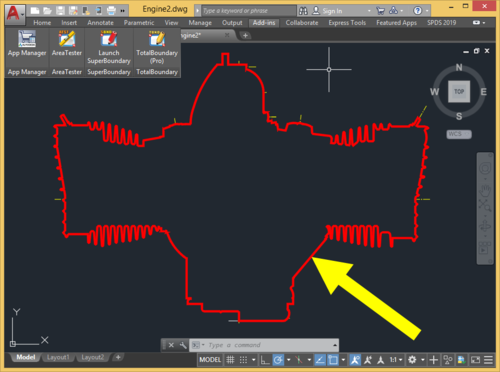
AutoCAD users often have to deal with the BOUNDARY (BPOLY) command, which allows creating boundaries (mostly enclosed polylines) from existing objects forming an enclosed area around the point specified. Unfortunately, its performance as well as the quality and the accuracy of the boundaries (contours) created when run in complex drawings leaves much to be desired. To eliminate these common drawbacks of the standard BOUNDARY command, a project called "SuperBoundary" was implemented. While BOUNDARY command generates simple contours quite efficiently in relatively simple drawings with a small number of objects on screen, SuperBoundary is intended to provide the user with comfortable workflow in drawings of any complexity. In other words, SuperBoundary is the utility based on the BOUNDARY concept supplemented by super-speed and some super-features. Key features: High performance. A powerful program engine allows analyzing and generating thousands of boundaries in seconds. High accuracy. When generating a boundary, all elements larger than the specified tolerance factor are considered. The possibility to create boundaries in areas having significant gaps between adjacent objects. The possibility to quickly detect and generate all the enclosed areas in the selected drawing or its part. Easy and accurate external outlines generation in complex drawings. Polylines generation from spline- and ellipse-based boundaries using piecewise-linear approximation Flexible adjustment of the boundaries generated. These are width, color and layer. Simple and convenient installation with classic installer. List of commands: _SBND - launch the app in classic mode _SBND_PICK - for quick usage in "pick point" mode _SBND_ALL - for quick usage in "build all" mode _SBND_CONFIG - for export / import current settings data as an external INI file1 point -
Version 2.1.30
7,405 downloads
AreaTester is a efficient plug-in for AutoCAD. It allows you to quickly measure the area in AutoCAD and gives you advanced capabilities to process the results of the calculations in the further workflow (annotate the the areas in the drawing, convert the received data to different spreadsheet formats, etc.). The plugin calculates not only the areas of enclosed objects, such as a polyline or circle, but also any other shapes formed by the intersection and connection of various types of objects, which include lines, arcs, splines and many other AutoCAD basic objects. At the same time, to calculate the area of any enclosed shape, you only need to point the crosshair of the cursor on it and the area value will be instantly displayed in the context window above the cursor. In addition, the user can create the necessary list of the areas in the main application window for the further workflow. All these areas are summed automatically in the created list. The total result of the summation is displayed at the bottom of the main window of the app. One of the main features of AreaTester, compared to the standard AutoCAD tools, is the ability to determine the area value of any bounded shape excluding the areas formed by objects that have got inside such an shape (the so-called "islands"). This option significantly simplifies the user’s work on calculating areas in AutoCAD, eliminating the need for additional mathematical operations. Key features of the AreaTester for AutoCAD plugin: Automatic calculation of the all areas in a drawing. Annotating the areas directly in a drawing. Drawing boundaries of the shapes in the form of polylines. Exporting the generated list of areas to the clipboard or some convenient data format (* .txt, * .csv). Adding the table of the area list to a drawing. For more information visit the official website of the AreaTester app.1 point -
CVPORT stands for "Current View Port" and when you type it should show something like the following. New current value for CVPORT (1 or greater) <2>: From your layout description type cvport when the right is active if its 2 change it to 3 and the left will then be active. You might not notice a change when typing them but if you use the zoom or pan only the active view port will change. You can also change Active view ports by just double clicking in the view port when their isn't an active command.1 point
-
This is for an Offshore Windfarm project. We have to bury an export cable, which transports the electricity from the offshore High Voltage station to the shore. But this is in the North Sea, which has a lot of sand waves, which are moving sand dunes under water. There are burial depth requirements for the export cable, but the moving sand waves (approx. 4m height difference) may cause that the cable is exposed after a couple of years because sand dunes are moving with the current. To prevent that the buried cable gets exposed, the client provides not only a bathymetry of the seabed, but also a non-mobile reference level which is a bathymetry of the part of the seabed that doesn' t move. The burial requirement of the cable is based on this non-mobile reference level (NMRL), which is much deeper than the existing seabed bathymetry. We bury the cable with a Trencher. This trencher is moving over cable (which is first layed on the seabed) and buries the cable (depending on the soil type) with either a big knife or waterjet. The problem is that this trencher has a maximum reach. If the Trench is burying at the top of a sand wave it may not reach the required burial depth. Therefor we first need to pre-sweep ( scrape away with a dredger) the top of all sand waves where the trencher can't reach the burial depth. We try to minimize the pre-sweeping depth to keep it as cheap as possible. There are along the 60km cable route a lot of sand waves...and there are often >2 export cables to bury. So we need to calculate the volume of pre-sweeped sand. Now here my routine steps in. We create in a CAD drawing 2 vertical profiles: 1 of the latest Seabed bathymetry and 1 of the Non-mobile reference level. The X-coord = the KP of the route and the Y-coord = the depth of the seabed or Non-mobile reference level (NMRL). We shift the NMRL line vertically upwards in such a way that at that level the cable trencher can achieve the burial depth requirement. Now the NMRL profile is intersecting the Seabed profile at the sand wave locations. These intersections are the start and end KP's to Pre-weep. However if the distance between a range of intersections (start and end KP's) is to small we remove the inner intersections. The main routine is used to create a list of KP ranges we use in DTM software to create polygons along the route to calculate the pre-sweep volume The Subroutine, removes the KP's where the distance between 2 intersections is smaller than e.g. 5m The 5m input is based on the size of the suction head of the dredger which pre-sweeps the sand waves. If a range of intersections is smaller than e.g 5m, then this location can be omitted because the head is larger than the area to be pre-sweeped Capice?1 point
-
@Quik&Easy - what is DRAGMODE set to on the machine where you can't see the entities being moved?1 point
-
I would suggest the following: (defun c:circles ( / i s x ) (cond ( (not (setq s (ssget "_X" (list '(0 . "CIRCLE") (if (= 1 (getvar 'cvport)) (cons 410 (getvar 'ctab)) '(410 . "Model")))))) (princ "\nNo circles were found in the active drawing layout or viewport.") ) ( (setq c (getpoint "\nSpecify new centre: ")) (repeat (setq i (sslength s)) (setq i (1- i) x (entget (ssname s i)) x (subst (cons 10 (trans c 1 (cdr (assoc 210 x)))) (assoc 10 x) x) x (append x '((62 . 1))) ) (entmod x) ) ) ) (princ) ) A few point to note on the above: I use a cond statemtent to test whether the selection set exists prior to evaluating other selection set functions (such as sslength) - else these functions will error if supplied with a null selection set. I use the second cond test expression to test the validity of the point supplied by the user, to account for the possibility of the user dismissing the prompt. I filter the selection set to only consider circles residing in the current layout/viewport, rather than in all layouts. Appending DXF group 62 is the easiest way to update the object colour: this accounts for the possibility of the object colour being set to ByLayer (in which case, no DXF group 62 entry will be present in the DXF data with which to use subst), and if an existing entry for DXF group 62 exists in the DXF data, this will be overridden by the last entry in the list.1 point
-
This app greatly saves my time! I often have to draw complex outlines of various rooms.1 point
-
you`ve put good use of the lisp, dcl here.. great1 point
-
Great solution! Suitable also for cadastral plans. Etc. The speed of work is particularly striking.1 point


