Leaderboard

Popular Content
Showing content with the highest reputation on 03/17/2021 in all areas
-
You can but it is only as information, it will never be accurate. This is one of the few circumstances where I would consider it acceptable to 'overwrite' a dimension which you can do in the properties palette (text override).2 points
-
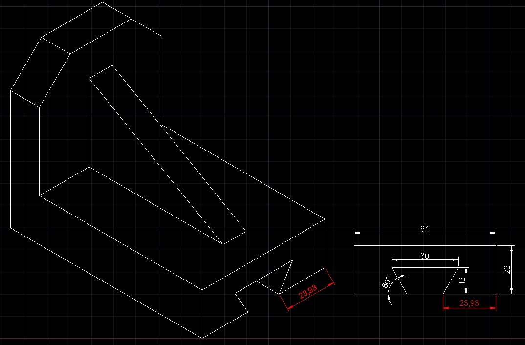
I think I see the problem, you are refereing to the 60° shown on the face of the isometric sketch. Yes correct that will never be drawn at 60° in the isometric view. It will only show up properly at 60° on the elevation drawing. The angle is shown there because you need to draw the elevation first in order to get the length of bottom pieces at the base (23.93). That size is the only dimension you are not given and you need to work it out yourself. So yes in isometric the angle will not show as 60° but somewhere about 39° when measured straight on, you cannoy draw using angles in isometric like that.
 2 points
 -
An isometric representation is not really 2D and not really 3D. It's just an illusion of 3D. By convention in an isometric drawing, a horizontal line is drawn at 30 degrees instead of 0. Vertical lines are still at 90. Distances are measured along those axes, so you get some unavoidable foreshortening. That is what's happening in your diagram. If you could build a 3D model and view it from the side, it would have a 60 degree angle. Since it's not 3D and you're not looking at it orthogonally, the angle doesn't appear to be 60. Because this is an illusion, there's no way to measure that angle directly. It's like trying to measure depth in a photograph, you're trying to get three-dimensional information out of two dimensions. Well, Irm ninjaed me, but between the two of us, maybe you can get the idea.2 points
-
Sounds like you may need to reset your settings to default. Close Civil 3D... The easiest way to do this is to go to your Windows Registry Editor. Browse to HKEY_CURRENT_USER\SOFTWARE\Autodesk\AutoCAD\R24.0\... There, you will see ACAD-4100:409. Right-click on it and delete it. Restart Civil 3D.1 point
-
Try: https://www.augi.com/forums/showthread.php?171905-Line-Cut-with-Symbol-(Tilde)&p=1336016#post13360161 point
-
OK this is something i already have for perimeter so i convert it for area. try and check . AEXPXL.Lsp1 point
-
I'm sure Lee mac has a copy text somewhere on this / his site but maybe post a dwg file so people know the structure of your blocks.1 point
-
maybe this can help you one step along the road : https://forums.autodesk.com/t5/visual-lisp-autolisp-and-general/select-a-cell-in-a-table/td-p/28926381 point
-
1 point
-
Post the drawing you have, and we can soon see where the problem is. No one is going to do your homework for you, but we will be happy to check to see if there are any problems.1 point
-
First of all, I do all the lisps I can myself and I made over 50 of them, and the problem here is populating one place in table. That I don't know how to do and tight schedule right now. And secondly, I didn't know there is a rule you can't ask if someone has that lisp when 90% of the people here do it and I don't have a problem with their requests and will help them if I can. But, nevermind my question, I'll do it myself somehow, thanks for your help Bigal.1 point
-
Is the persistent tag inside a block or is it a free-floating attribute? If it's inside a block, it should disappear after a purge. Did you run ATTSYNC to standardize the block definition? Is the new tag inside a block?1 point
-
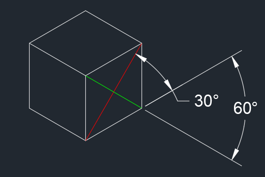
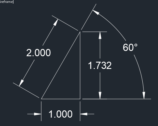
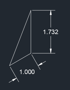
@Cadbuddy when creating an isometric drawing you cannot use the "real" angles to draw lines at an angle. Consider the following. A cube that has side lengths of 1 would look like the image below. The red and green lines are diagonals on one face of the cube. We know that for the real object these lines would be at an angle of 45° relative to the cube's edge. Look at the real measure angles. For the red "45°" line we measure 1 unit up to the right and then 1 unit straight up. For the green "45°" line we measure 1 unit down and then 1 unit up to the right. We know that a 30-60 triangle has sides of 1 and 1.732 (square root of 3) and a diagonal of 2. To draw the 60° line in your isometric measure 1 unit at an angle of 30° then up 1.732 as follow. Trim the resulting line as necessary.
1 point
-
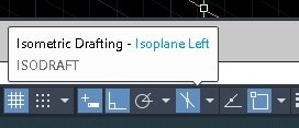
There is an Icon on the lower right of your screen it toggles on/off isodraft, and the drop down arrow just to the right of that will let you pick left/right/top. This tool is designed for creating isometric drawings. If for some reason you don't see the Icon, then on the far right of the taskbar you see 3 horizontal lines, click on that and select 'isometric drafting' from the list.
1 point