Leaderboard


Popular Content
Showing content with the highest reputation on 03/15/2021 in all areas
-
Hi @rkmcswain and all who have commented - thanks for your kind words. It has been a pleasure to keep this forum in good order over so many years (the CADTutor site is 25 years old this year!). Naturally, a forum isn't anything without its members, so I thank you all, in return, for being such a great community who continue to post brilliant content and .give your time freely to help others. Long may it continue!4 points
-
Just a note to say thanks for maintaining this site. It's a pleasure to come here, read a question, type out a response and see it instantly appear to help the other user(s). Image attachments via drag+drop work flawlessly too. It is noticed and appreciated. Cheers!2 points
-
I wasn't aware there were any others. I must get out more!2 points
-
Also the best users, mods and admin!2 points
-
In AutoCAD those are only display settings, the actual dxf contains an arc. It sounds like your CNC software is converting the arc to segments I would ask in the Forums for Mach3 if there is a setting that needs adjusting. It sounds like the software that is producing the g-code is causing the problem, is that Mach3 or do you have another piece of software in the middle of the process.1 point
-
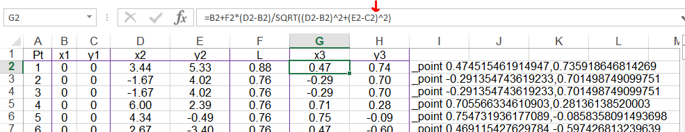
@jay@sitetechnologies.io I had a typo in my spreadsheet. Here it is corrected in your Excel file. A similar correction is required in H2 before you fill down. =C2+F2*(E2-C2)/SQRT((D2-B2)^2+(E2-C2)^2) You can copy and pasted the AutoCAD commands in column into the AutoCAD prompt llne to create the points. SolvingPointC.01.xlsx
 1 point
 -
If want an excel solution could use a ratio answer have pta 0,0 & ptb x,y so work out length pta to ptb then desired length/ total length. Something about an old guy pythagoras. Now (ratio * x2) (ratio * y2) then add to 0,0 thats the new point co-ordinates.1 point
-
Here is a basic function and test command. I am using an association list in the form of (list (cons PtB L)(Cons PtB L)...). I leave you to figure out how to gather the points/Length list. ;; pllst = Association list of Points and Lengths. Example: '(((1.0 1.0) . 0.435)((2.0 2.0) 1.267)((3.0 3.0) 2.723)) (defun Get_Lpoint_List (pllst / rlst) (vl-load-com) (if (and (= (type pllst) 'LIST) (vl-consp (car pllst))) (foreach pt pllst (setq rlst (cons (polar '(0.0 0.0) (angle '(0.0 0.0) (car pt)) (cdr pt)) rlst)) ) ) (reverse rlst) ) (defun C:testthis (/ lst) (setq lst (list (cons (list 1.0 1.0) 0.435)(Cons (list 2.0 2.0) 1.267)(cons (list 3.0 3.0) 2.723))) (foreach n (Get_Lpoint_List lst) (command "._Point" "_non" n) ) )1 point
-
Ditto !1 point
-
I agree also great forum, the biggest out there is the worst site and they just dodge around the edges of the problems by saying contact our support request department1 point
-
Like Lrm its very simple pick a line from 1 end that becomes ptA something I have been doing for years. ; simple make a point at dist on a line ; By AlanH march 2021 (defun c:testpt ( / tp1 tpp1 p1 p2 p3 d1 d2 temp ang ) (SETQ TP1 (entsel "\nSelect Line near left end: ")) ; implies which way (setq tpp1 (entget (car tp1)) p1 (cdr (assoc 10 tpp1)) ; start point p2 (cdr (assoc 11 tpp1)) ; end point p3 (cadr tp1) ) (setq d1 (distance p1 p3) d2 (distance p2 p3) ) ; swap point direction for end closest (if (> d1 d2) (progn (setq temp p1) (setq p1 p2) (setq p2 temp) ) ) (setq ang (angle p1 p2)) (setq d1 (getreal "\nEnter distance from end ")) (setq pt (polar p1 ang d1)) (setvar 'pdmode 33) ; turn on point style (command "point" pt) ; create a point (princ) ; exit quietly ) A couple more options are pt offset sq from point, and pt along a pline as already mentioned.1 point
-
Since point A and B are connected by a line, you could just have "select line" and work out the points?1 point