Leaderboard

Popular Content
Showing content with the highest reputation on 03/08/2021 in all areas
-
Something like this ? (defun c:Test (/ p l a) (while (setq p (getpoint "\nSpecify point :")) (setq l (cons p l) a (car l) ) (foreach q (cdr l) (grdraw a q 3 -1) (setq a q) ) ) (redraw) (princ) )1 point
-
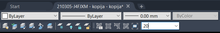
Being metric and working in metres it is very easy to work out a plot in a layout. Like Steven-g have your title blocks as true size in mm as he has provided, make a mview now for the nice bit make sure you have the "Viewports" tool bar turned on. The box tells you what scale the view is when you click inside. So for 1:50 just zoom to about what you would like to see then in the viewport toolbar box put 20 the viewport will rescale to 1:50. Now why 20 simple take 1000/scale so 1000/50 = 20 1:250 = 4 1:100 = 10 its just so simple.
 1 point
 -
You had started the drawing with a metric template setup in millimeters which means layouts and viewportscales also use millimeters. I changed your drawing units to meters using the '-dwgunits' command but scaling the paperspace viewports also changes you dimension styles so it was easier just to add in new layouts for standard paper sizes and edit the scales manually (normally you should create a template set with everything ready to use meters but that is a topic of study all by itself). Attached is a copy of your file showing A1 - A4 all at 1:50 210305-J4FJXM - kopija - kopija.dwg1 point
-
Do you know anything about paper space or viewports? This is a concept that most people struggle with who are new to the program. There are many video tutorials on youtube that go in depth and cover the whole process of setting up viewports for printing. I would suggest that you watch a few tutorials and then come back with specific questions about anything you don't understand.1 point
-
Do you have your layouts set for the paper size you will be using? And did you setup the drawing units before you started? typically in a metric drawing everything is expecting millimeters as the drawing unit so all your scales will be set according to millimeters. Just changing the units to meters with the 'UNITS' command isn't enough you need to run the '-DWGUNITS' (with the hypen "-") and AutoCAD will adjust the scales for you. It will be a lot easier if you could post the drawing file here so someone could check your settings, but we do need to know the 'paper' size and the area of the drawing that needs to be plotted often people say they want to plot something at 1:50 but it just doesn't physically fit on a sheet of paper they want to use at that size.1 point
-
As I use it in a few dozen macros many times a day for importing layouts, plot styles, page setups, dimension styles, etc… I load it in acaddoc.lsp. Example ^C^C^P(Steal (strcat (vl-filename-directory (getenv "QnewTemplate")) (chr 92) "AutoCAD Template" (chr 92) "Templates.dwt") (list (list "Page Setups" (list "11×17" "11×17 PDF")))) .regen1 point
-
Civ3D is like this also, anyway To Purge Styles | AutoCAD Architecture 2018 | Autodesk Knowledge Network1 point
-
I use (if (not StealAll)(load "StealV1-6")) at start of your code this way it loads Lee's steal lisp and all the steal code does not live in your lisp program.1 point
-
In the words of CAD Manager extraordinaire Mark Kiker .... "Don't let a management problem become a technology problem" In other words, this sounds like a management problem. Tell the designers to not unlock these layers, problem solved. Unless of course you have 1,500 of them and it's virtually impossible to tell who is doing it, and therefore you don't know who to write up. On the technical side, I suppose it's possible to load 3rd party code with a reactor that can detect when a layer is modified, record the modification, and the current user at the time, to a log file. Layers cannot be locked with a password inside of ACAD. You could export those layers to a separate DWG file, then place those DWG files in a network location to which these rogue designers do not have write access, then xref them back in.1 point
-
Oops! Here is a correction: Tested with other polylines (defun c:ML2TXT (/ en en2 ss) (if (and ; Mark the last entity in the drawing. (setq en (entlast)) ;; Select the Multileader(s) (setq ss (ssget '((0 . "MULTILEADER")))) ) (repeat (setq cnt (sslength ss)) ;; Get 1 MLEADER from the selection set. (setq en2 (ssname ss (setq cnt (1- cnt)))) ;; Explode the MLEADER (command "._explode" en2) ;; Loop through the newly created entities. (while (setq en (entnext en)) ;; if a line, polyline or solid, delete it. (if (wcmatch (cdr (assoc 0 (entget en))) "*LINE,SOLID")(entdel en)) ) (setq en (entlast)) ) ) (princ) )1 point