Leaderboard
.thumb.jpg.09a08ecad2685cb2c8053165bd65e191.jpg)
Popular Content
Showing content with the highest reputation on 12/11/2020 in all areas
-
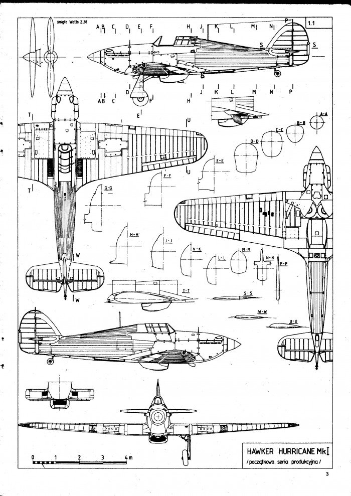
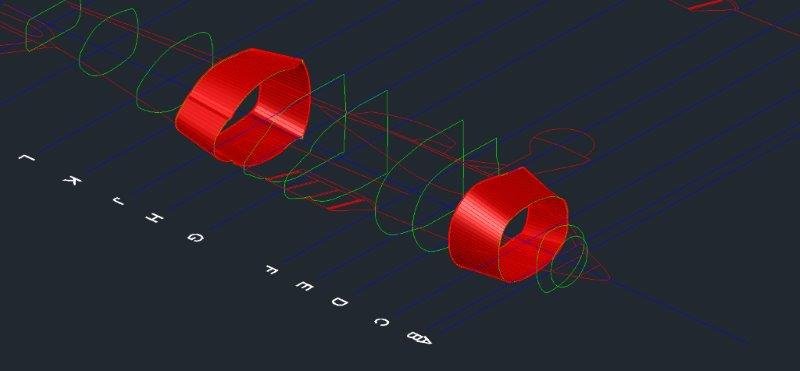
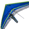
I am currently wasting time by modeling a hawker hurricane in 3D in AutoCAD 2016 (see attached). I found the plans online that included cross sections and I am essentially trying to use RULESURF command to mesh between the closed polylines at each cross section of the aircraft. Sometimes, this results in the mesh becoming twisted up on itself like a tin can. However, sometimes the results are decent - fore example, these two surfaces are OKish. HawkerHurricane.bmp Loft sometimes works between these surfaces but a couple times it has crashed AutoCAD and not sure why. To trace out the cross sections I sometimes used splines and arcs and eventually used pedit to convert everything to polyline and close it up. SO methinks my level of detail on the polylines might be what is crashing CAD when I use Loft on some of these. Does anyone have any tips on how to get RULESURF to work properly? Currently, my SURFTAB1 = 96 and SURFTAB2 = 96. I am going to go back to the wings once the fuselage and canopy are modeled. I am planning to use a similar modeling technique and use cross sections of the wing every foot or two. Once one wing is comlete I will mirror it over, basically. Thanks! -ChriS HawkerHurricane.dwg
 1 point
 -
If I understand correct (defun c:test ( / obj1 obj2 co-ord end start) (While (setq obj1 (entsel "\nPick rectangle Enter to exit ")) (setq obj2 (vlax-ename->vla-object (car (entsel "\nPick other line ")))) (setq co-ord (mapcar 'cdr (vl-remove-if-not '(lambda (x) (= (car x) 10)) (entget (car obj1))))) (setq end (vlax-curve-getendpoint obj2)) (setq start (vlax-curve-getstartpoint obj2)) (if (> (distance (nth 0 co-ord) start) (distance (nth 0 co-ord) end)) (command "point" start) (command "point" end) ) (setvar 'pdmode 35) ) (princ) )1 point
-
You fed them after midnight, didn't you? Never feed them after midnight. And whatever you do, don't get them wet.1 point
-
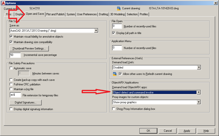
Most likely a change to DEMANDLOAD System Variable, should be 3 IIRC. Or in Options>Open and Save>ObjectARX apps: Object detect and command invoke
1 point
-
This tutorial shows how to design a fighter aircraft in Solidworks surface field. Watch there help you do it. Full HD tutorial video: https://youtu.be/GrmaTRVixwU For more information FB: https://www.facebook.com/SolidworksShare/ ----------------------------------------------------------------------------------------------------------------------------------------------------------------------------------------------------------------------------------1 point
-
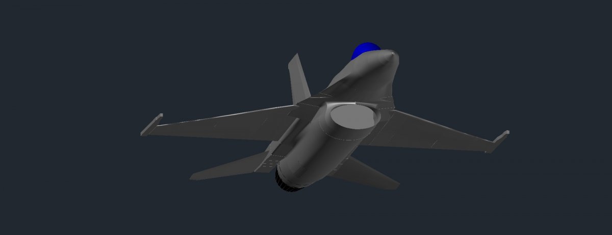
I did this last year with autocad lol. But it was less of a tutorial more of a journal of what problems i had. The easiest way is to find a drawing that shows cross sections every foot or two. You insert those at the correct location and it is kind of like you are actually building the actual plane only with 3d objects or meshes. Loft command works between cross sections. As does rulesurf to interpolate the mesh shape. You only have to model half the plane and mirror it all at the end. I was able to find the manufacturer's drawings online for the F-16E with evenly spaced cross sections (not sure how but it was on the web lol). I was originally gonna do a hawker hurricane but had some problems and f-16 seemed more fun. Autocad actually did a surprisingly good job. Although solidworks would look really neat too. I have attemped a B1 and an F117. Had more success with the F117. The sharp linear edges of an F117 lend themselves well to modeling in something like Autocad as well. The neat part about this kind of project is you are modeling the aircraft 1:1 scale as it was intended by the manufacturer so it comes together in model space as it was intended too. SO you feel like you are building a real-deal scale model which is fun. This is the kind of thing I was doing last year. I got hired on to a design firm in Anchorage, Alaska but they didn't have anything to do. So for like 3 or 4 months I did this to make myself look busy. IT IS challenging. And it is a problem solving test. It forces you to retain your ability to think geometrically. Your mind itself becomes model space.1 point
-
How about this?
1 point
-
Sorry bout that here you go lol. ChriS
1 point
-
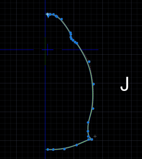
Rather than using polylines for the sections I think you should consider making the half section single splines. Are you comfortable with the manipulation of Fit and CV points of a spline? If not, you might consider "tracing" some of your polyline profiles, or the pdf drawing to create a spline that is a satisfactory representation of the shape. I would start by creating a spline using a dozen or so fit points along the profile. Do not worry about the resulting curve duplication the original. Use close together fit points where there are abrupt changes in curvature. Use few fit point where the curve is relatively smooth. The fewer the fit points the less likely you will get undesired ripples. The next step is to change the editing mode to Control Vertices and see how you can improve the fit by moving the CVs. Use splinedit e a to add additional CVs if they are needed. If you need a sharp corner in the spline then drag two CVs so that they are coincident. I am in the habit of creating profiles in a CCW direction. In 3ds Max this ensures that surface normals are pointing outward and reduces confusion later in the modeling process. The attached file includes your polyline profile (green) for station J and a spline (yellow) I quickly created. It needs some tweaking but you can get a feel for the CV layout. It is important to note that the first two and last two CVs of a spline control both the radius of curvature and the slope of the spline at the ends. If you do not want a crease at the bottom of the fuselage for instance, make sure that the last two CVs are in line horizontally. Your polyline has 546 vertices while the spline has 28 CVs. I think you will find you will get a better quality solid model using splines and not polylines. section-J.dwg
1 point
-
I see a few major problems with your profiles. 1. The starting points for each profile are not consistent. The yellow dot shows where each polyline starts. YOu want them all to start at the same relative position (e.g., bottom corner or center top, or...). 2. The polylines do not go in the same direction. G,H,and J are clockwise whereas K and L are counter clockwise. They should. 3. The polylines have way too many vertices. 478 for L, 544 for K, etc. ! I think creating half profiles and mirror after making a solid is a good strategy.
1 point
-
Re: Cut & Fill. The instructions are vague in my opinion. I would definitely contact the instructor and ask for clarification. When I did highway drafting for a major consulting firm our cut and fill profiles were done at various stations along the highway centerline and would extend to either side of it a minimum distance of 100 feet. Re: Sections A & B. The student is expected to create a grid with stationing along the horizontal axis and elevations along the vertical axis then plot the centerline profile (contour intervals) as they intersect with the driveway centerline. BTW...the vertical and horizontal scales in most instances will not be the same. For example, the horizontal scale could be 1"=40' (a typical engineering scale) while the vertical scale might be 1"=4'. I believe Section A will have a horizontal scale of 1"=60' while the vertical scale will be 1"=10'. I also believe P-F calls for the same scale, 1"=10', to be used for both the horizontal and vertical in Section B.1 point