Leaderboard

Popular Content
Showing content with the highest reputation on 11/23/2020 in all areas
-
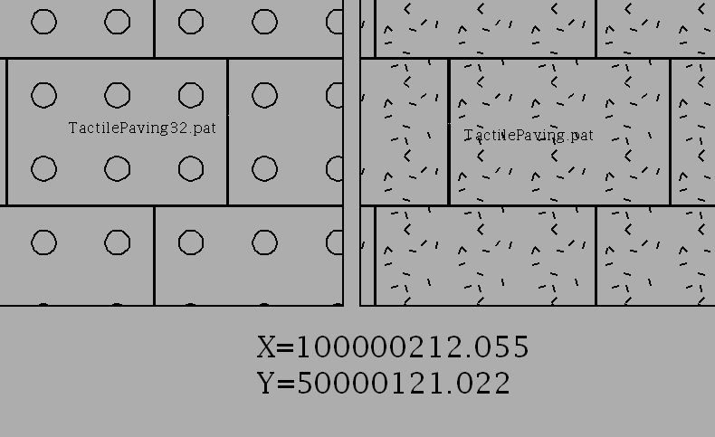
Not having had much practice with circles in hatch patterns, I thought I would try to use a 32 sided polygon (a triacontadigon) in the hatch pattern and see how much accuracy I could get. This makes a difference when the hatch is a long way from 0,0. Examining the format of the hatch pattern definition, there are angles, coordinates and distances. When one moves far from 0,0 accuracy of the angles is important because the effect is magnified and so are the distances. The coordinate is only the start point of the hatch pattern and thus can be less accurately defined (3 decimal places). One needs to aim for 10 decimal places for angles and distances, but also bearing in mind that the maximum length of a single line of definition is 80 characters. Because AutoCAD can only display angles to 8 decimal places, I thought to improve that accuracy by trigonometry. When one tweaks the direction of each side of the polygon to aim at the next pattern shape, the tangent of angles can always be defined by integer values. So too the distances. Thus with a spread sheet, one can calculate angles and distances more accurately then AutoCAD can display them. I managed to rewrite the Tactile Paving hatch pattern with a 32 sided circle with as many decimal places that I could and called it TactilePaving32.pat. As this was a bit of a trial for me, I will not be posting the actual definition file unless someone can't live without it! The picture below shows some hatches a long way from the origin (coordinates shown) of the two hatch patterns - TactilePaving and TectilePaving32. One can see how less accurate my first hatch pattern was (bits of line spread out all over the place), but as long as it is used close to the origin, it should suffice. But the latest file TactilePaving32 shows almost no separation of the hatch elements.
 1 point