Leaderboard


Popular Content
Showing content with the highest reputation on 09/25/2020 in all areas
-
Looks great! I'm always impressed by the renders that come out of this free program.1 point
-
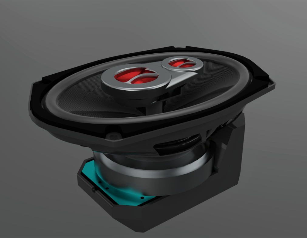
I like it. My 20 year old son is in to speakers and such so I'll show him your work. He made a sub box for a friend of his that doesn't have a lot of money and we used the CNC machine at work to carve in the logos on the top. The kid almost cried when he saw it. Any way here's 5 minutes of work in Simlab Composer Lite (free) with materials and a 2 min 30 sec render.
 1 point
 -
I completely forgot about that program you use. I should have suggested it before jumping through all these hoops with Autocad. Looking forward to seeing your render.1 point
-
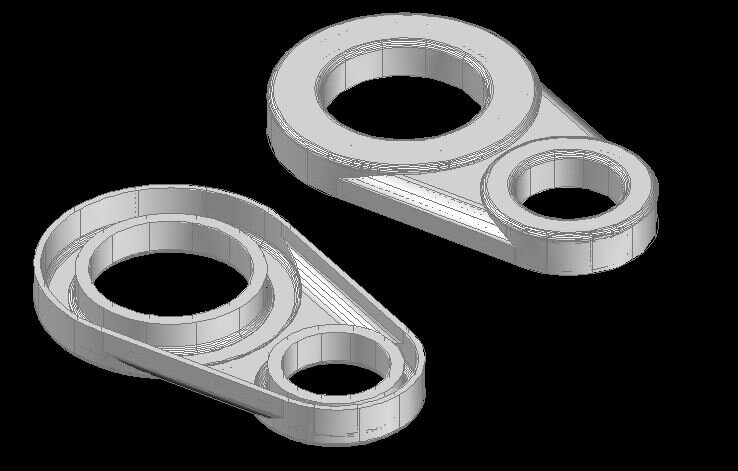
Believe or not I went searching for a 3D drawing of a 6X9" speaker on the internet and couldn't find one. So now there is a 3D drawing for a 6X9" speaker even if it's just close.1 point
-
I'm working on my layers now. My way of thinking was like when I was in sawmill equipment, they would give us a layout drawing and we would get prints to make parts, frames, rollers and all the things we needed to build it all. We would lay it out on a floor, as the things were welded, fabricated, machined we put them together in that spot till the mill was all there. That's how I got my idea of how to do it. @f700es There is a .DWG on page 5 of this thread, I believe.1 point
-
Don't use AutoCAD to render. Yes I know it can do it BUT there are better and easier solutions. Give me your cad file and I'll show you Great job on the model BTW. It looks great. Edit: I see the dwg, nevermind1 point
-
I used align. To make this work, I first drew a polyline from Base Point 1 to the realignment point, then I drew a polyline from Base Point 2 to the realignment point. By drawing polylines, I ensured that the z value of the Base point was the same at the realignment point. Then using align, I selected all the road strings and used each end of the polylines just drawn for the source points. Job done.1 point
-
The parts look great. Too bad the actual printed part broke. But, that's all part of R&D. If at first you don't succeed. Try, try again.1 point
-
After 2 days I'm close. I don't like the color but I'm learning how to edit materials.
1 point
-
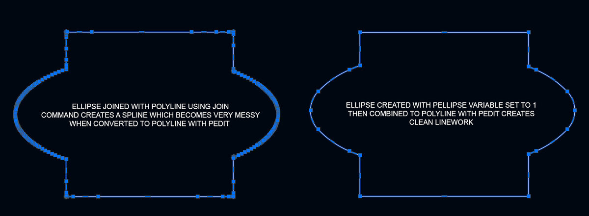
I'm not a big fan of splines. When you convert a spline to a polyline you get messy geometry with lots of excessive grips, which then translates into a messy 3D object when you extrude it. I don't know if that would cause any issues with a 3D printer, but I always try to keep my geometry as clean as possible when working in 3D.
1 point
-
If you want to use ellipse's and be able to join them to a polyline, you have to first change the setting of the PELLIPSE variable to 1. This tells Autocad to create the ellipse as a 2D polyline. The default setting is 0 which creates the ellipse as a 'True ellipse', which can't be used in a polyline.1 point